SSZT890 November 2017 LM3880
I hope you enjoyed the last blog on rail requirements. Now we move on to sequencing, another important topic in field-programmable gate array (FPGA) power design. While powering the FPGA on and off, the power supplies need to turn on in a particular order. The exact sequencing series will vary, but typically the core rail is the first on and the first off. The turning on of the power supply has to be monotonic, which means that there is a continual rise in output voltage powering the FPGA. Finally, there are requirements for how quickly everything needs to fully power up from start to finish: typically, all rails need to get to 95% within 40 or 50ms. In this blog post, I will review three common techniques for sequencing.
The first and most simple technique is resistor-capacitor (RC) sequencing, depicted in Figure 1. When a power supply turns on, the RC time constant will drive when the device turns on. This means that you can simply adjust the RC values for each power supply, which allows you to stagger the turn-on. As you can see in Figure 1, the power supply with the lower RC time constant will turn on first. Another similar technique is adjusting the soft-start so that some power supplies turn on more slowly. However, these techniques cannot support power-down sequences and can be unreliable during temperature variations, or if there are any faults causing incomplete or repeated power cycles.
 Figure 1 RC Sequencing
A much more effective and reliable technique is cascading power supplies as seen in Figure 2. In this technique, you connect the output of the first device’s power-good pin into the enable pin of the next power supply to turn on. This means that when the first device’s power good goes high, it triggers the next device to turn on. This technique is more reliable than basic RC sequencing; however, it still cannot support a power-down sequence.
 Figure 2 Cascading Power
Supplies
Figure 2 Cascading Power
SuppliesThe final sequencing technique, shown in Figure 3, uses the microcontroller (MCU) for sequencing. This method requires software and uses a timer, general-purpose input/outputs (GPIOs) and the bandwidth of the MCU. The MCU provides a brain that senses the output voltage of each power supply and then tells the next device to start turning on (or off) based off the programmed sequence. This is the most complex technique, but it provides the most amount of control and gives you the ability to program both the power-up and power-down sequences.
 Figure 3 MCU Sequencing
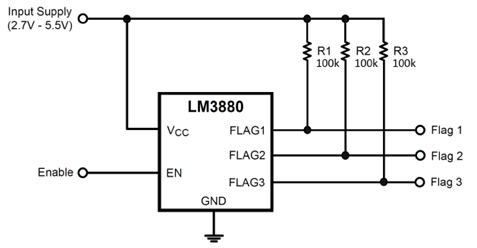
Another potential solution is TI’s LM3880 simple sequencer. The LM3880 has three rails to turn on or turn off three devices by manipulating the values of R1, R2 and R3, as shown in Figure 4. This provides a simple way to sequence if you need something more reliable than the first two techniques and don’t have the MCU bandwidth to implement the third technique. You can daisy-chain the LM3880 to support the sequencing of more than three devices if necessary.
 Figure 4 LM3880 Simple
Sequencer
Figure 4 LM3880 Simple
SequencerAfter choosing a system architecture, understanding the rail requirements and choosing a sequencing strategy, you should now have a better understanding of what key features and performance metrics you need for your power supplies and can start selecting parts. I’ll cover this in the next and final installment of this series on FPGA power.