SSZT901 November 2017
In the first two installments of this series, I looked at how zero-wait-state transfers and multiport analog-to-digital converter (ADC) reads help C2000™ microcontrollers (MCUs) scavenge cycles at the sensing stage of real-time control systems. In this installment, I’ll remain focused on sensing and look at how ADC start-of-conversion timing and configurable ADC interrupt delay differentiate C2000 MCUs from competitors in terms of real-time control performance.
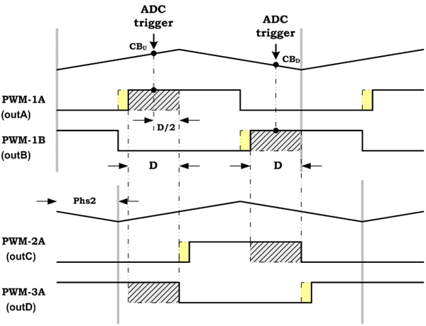
Let’s start by looking at ADC start-of-conversion timing. C2000 MCUs allow an ADC start-of-conversion trigger at any point during the pulse-width modulation (PWM) period, not just at the frequency or duty-cycle counts. This enables you to time the ADC conversion to exactly when the (CPU) is ready to use the data. The timing diagram shown in Figure 1 illustrates this feature.
 Figure 1 ADC Start-of-conversion Can Be
Triggered at Any Point During the PWM Period
Figure 1 ADC Start-of-conversion Can Be
Triggered at Any Point During the PWM PeriodSince the enhanced PWM (ePWM) module lets you place the trigger anywhere, you can sample your data just before you need it. This not only ensures that the ADC samples are as “fresh” as they can be for the control algorithm, but also helps reduce the sample-to-output latency, which is the ultimate goal in real-time control systems.
Configurable ADC interrupt delay is a new feature on the C2000 F28004x series that allows you to specify an exact delay time between the start of conversion and the setting of the interrupt flag. In order to understand how this helps with saving cycles, consider the following scenarios.
Say the ADC interrupt triggers at the end of the ADC conversion when the result is ready. It would then take around 14 cycles for the CPU to context-switch into the interrupt service routine (ISR). This is wasted time considering that the control algorithm doesn’t handle the ADC result for 14 cycles after it is ready. From a real-time control perspective, such an approach would be unacceptable due to the added sample-to-output delays.
You could trigger the ADC interrupt at the beginning of conversion. The issue with this approach is that you get to the ISR early and the ADC result might not be ready. You would then need to wait until the result is available, which again burns cycles. So this approach is not suitable for time-critical loops either.
With configurable ADC interrupt delays, C2000 MCUs enable you to trigger the ADC interrupt at exactly the right time so that the ADC result latches into the result register exactly one cycle before you need it. Being able to enter the ISR at a programmable time is significant from a cycle-scavenging point of view because it can squeeze cycles out of the sample-to-output latency, without wasting CPU cycles waiting for ADC samples to be ready.
In the next installment, I’ll look at the ADC post-processing block, which can help save a significant number of CPU cycles that would otherwise be required in the middle of your most time-critical loops.
Additional Resources
- Keep up to date with our cycle scavenging blog series here.
- Download the technical reference manuals for TMS320F28004x Piccolo™ MCUs and TMS320F2837xD dual-core Delfino™ MCUs.