SSZT903 November 2017 TIC12400-Q1
Today, we have vehicle types that didn’t exist years ago. We have compact SUVs, coupes, convertibles, minivans and trucks. It goes beyond vehicle types as well; cars offer a variety of safety functions (blind-spot detection, tire-pressure monitoring, adaptive cruise control) and comfort systems (infotainment, climate control) to enhance the transportation experience with customizable bells and whistles.
The number of keys and buttons on an automobile has increased as passengers have more control over their comfort (see Figure 1). This increase in user inputs has complicated body control module (BCM) design, now that more inputs directly connect to and are monitored by the microcontroller (MCU) on the board, all with an increased potential to fail. One way to address these inputs is to add more discrete components to share inputs with an analog-to-digital converter (ADC), comparator and/or input/output (I/O) expander to enable more I/Os. Another option is an integrated solution like the TIC12400-Q1 – a solution that specifically integrates an ADC to simplify designs, save system costs, and ultimately let drivers and passengers control their own riding experience.
 Figure 1 Early Automobiles Had No
Keypads, Whereas Today’s Cars Have Three or More
Figure 1 Early Automobiles Had No
Keypads, Whereas Today’s Cars Have Three or MoreIn this blog post, I’ll cover an efficient keypad design using the TIC12400-Q1.
The easiest way to evaluate a push-button is to connect it directly to the I/O pin of an MCU. This is the best solution if a single MCU only needs to evaluate a couple of push-buttons. MCUs usually have eight to 32 I/Os, but with an increasing number of switches, the number of I/Os on the MCU pins increases accordingly. In many cases, this leads to a need for larger (and therefore more expensive) MCUs. A solution to this problem is “matrix mode.”
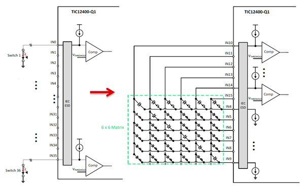
Setting up input switches in a matrix configuration reduces the number of I/O pins required for an application by up to 62.5% (64 switches with 24 pins) (see Figure 2). By placing the switches into a matrix configuration, the number of I/O pins can be reduced to the total number of columns (IN10 through IN15) plus the number of rows (IN4 through IN9) in the switch matrix.
 Figure 2 Benefits of Using the
TIC12400-Q1 in Matrix Mode
Figure 2 Benefits of Using the
TIC12400-Q1 in Matrix ModeUsing a 4-by-4 matrix, you can monitor as many as 16 push-buttons using only eight I/O pins. With a conventional solution (where a single push-button connects to one I/O pin), you can evaluate only eight push-buttons. With more push-buttons, a switch matrix will lead to even greater savings in the number of I/O pins required. For example, a 6-by-6 matrix of switches has 36 total switches but only requires six sourcing columns and six sinking rows, for a total of 12 I/O pins. This feature means that changing from a single push-button per I/O switch configuration to a 6-by-6 matrix configuration saves 24 I/O pins.
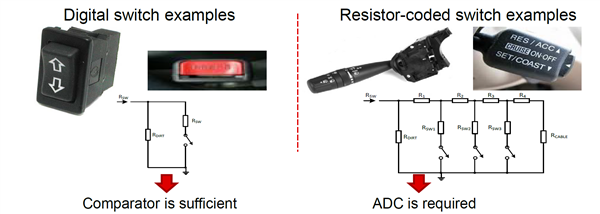
You can use the built-in ADC and comparator to monitor resistor-coded switches or digital switches (see Figure 3). Digital-switch inputs have only two states – open or closed – and can be adequately detected by a comparator. Resistor-coded switches may have multiple positions that need detecting, and an ADC is appropriate to monitor the different states. You can individually program each input of the TIC12400-Q1 to use either a comparator or an ADC. TI provides a very easy-to-use graphical user interface (GUI) that interprets which button is pressed. You can, with the help of the GUI, decide whether to use the comparator or the ADC and assign different threshold values to the ADC.
 Figure 3 Comparator vs. ADC
Detection
Figure 3 Comparator vs. ADC
DetectionThe benefit of using a comparator instead of an ADC to monitor digital switches is the comparator’s reduced polling time, which translates to overall power savings when the device operates in low-power polling mode.
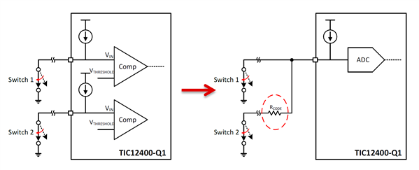
You can use input sharing on channels 18-23, since they have more than three thresholds that you can set up to detect four different switch states from Switch 1 and Switch 2 (see Figure 4). You can add up to six additional inputs using resistor-coded switches for a total of 30 channels.
 Figure 4 Input Sharing on the
TIC12400-Q1
Figure 4 Input Sharing on the
TIC12400-Q1The TIC12400-Q1 is a great solution for applications that need many inputs monitored.
Additional Resources
- To read more about MSDI, BCM design and industry trends:
- The multi-switch detection interface: integrated features for smaller, more efficient designs
- Body control modules – invisible but fundamental for every car
- Check out the Automotive Multi-Switch Interface Reference Design
- Watch the TIC12400-Q1 in action
- Learn more about Automotive gateways: the bridge between communication domains