-
Comparing Capacitive and Ultrasonic Kick-to-open Sensing
Comparing Capacitive and Ultrasonic Kick-to-open Sensing
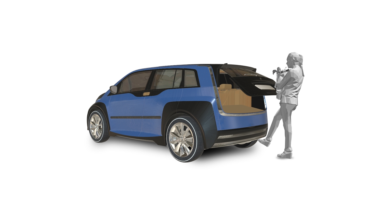
Automotive manufacturers are using both capacitive and ultrasonic sensing in “kick-to-open” features and parking-assistance applications. As part of a passive-entry, passive-start (PEPS) system, these sensors can add convenient hands-free operation to sliding doors, hatchbacks and trunks.
Because both the capacitive and ultrasonic sensing methods of detecting changes in the environment near a car have their respective advantages, let’s compare them.

Similarities
First, let’s look at the similarities. Both sensing methods are of interest when you want to determine the presence of an object without touching it (noncontact sensing). Both capacitive and ultrasonic sensing use an oscillating (vibrating) waveform to detect a nearby object; for capacitive sensing, the oscillation is in the form of an electromagnetic field that is affected by nearby objects. For ultrasonic sensing, the oscillation is in the form of an acoustical sound-pressure wave that bounces off the object in order to measure an echo. Neither method requires the object being sensed to itself transmit any energy; in other words, the sensed object can be “passive” when providing a signal to the sensor.
Kick-to-open applications differ from other noncontact measurements in that the system is looking for a brief change in the environment around the sensor rather than making a true distance measurement, as with parking-assist or liquid-level measurements. Therefore, both capacitive and ultrasonic methods can identify the approach of nearby objects without necessarily making a precise determination of the distance to the approaching object.
Format of Response
Now let’s look at some differences between the two sensing methods.
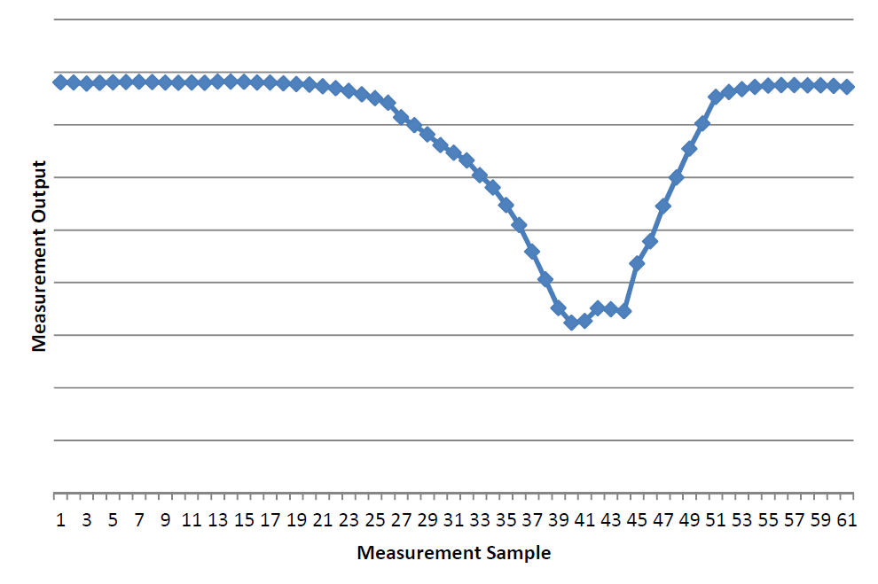
The response of a capacitive sensor is a scalar quantity. For each sample in time, a capacitive sensor provides a single value representing the measured capacitance (or variable oscillation frequency). This single value represents the total capacitance sensed, whether due to a single object or several objects. Figure 1 shows a sequence of 61 samples from a capacitive sensor during a kicking gesture.
 Figure 1 Example Capacitive Sensor Response During Kicking Gesture
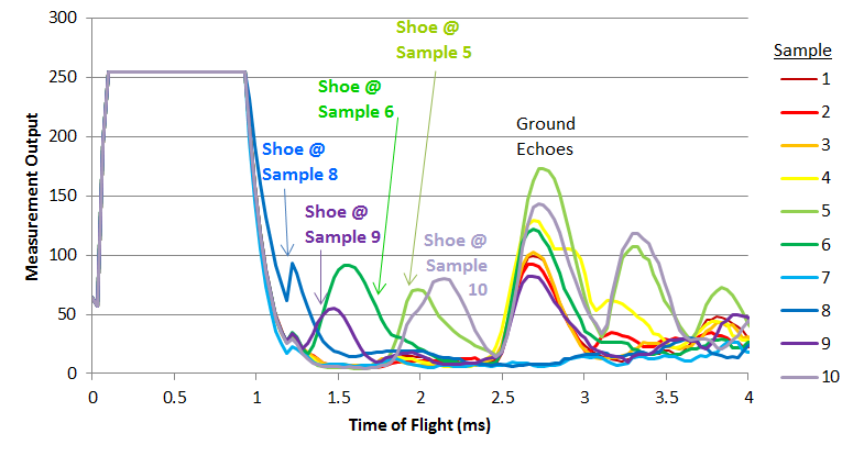
On the other hand, the response of an ultrasonic sensor is typically a vector quantity consisting of a set of ordered pairs of time and echo amplitude. Each pair indicates a measure of the distance from the transducer to the object and the size and reflectivity of that object. Thus, the response from an ultrasonic sensor may individually show more than one object in its field of concern, along with the distance to each object. The inclusion of reported distances enables designers to “tune out” objects at certain ranges and pay more attention to objects at certain distances. Figure 2 shows a sequence of ten response vectors from an ultrasonic sensor.
 Figure 2 Example Ultrasonic Sensor Response During Kicking Gesture
Placement of Sensor and Field of Sensitivity
Because humans will activate the kick-to-open system, the sensing design must consider the size and shape of the field of sensitivity of the sensors. The field of sensitivity of an ultrasonic sensor is typically a three-dimensional cone-shaped volume emanating from an ultrasonic transducer. For applications where the sensitive area has a short distance, the cone will have a limited size, but multiple transducers can be used to increase the sensitivity area. Because only a sensor exposed to the air can effectively transmit and receive ultrasonic energy, ultrasonic sensors must typically be mounted on a car’s exterior, such as in holes through the bumper cover.
For capacitive sensors, the antennas can vary in shape; the field of concern is then the volume around each antenna in all dimensions. One common approach is to use linear antennas, which provide a length of sensitive area; a linear antenna has a cylindrical field of sensitivity. By default, the sensitive volume includes the body of the automobile, but adding a ground plane can shield the antenna from most of the effects of the car, such as changes in electrical field due to lights or motors.
Ultrasonic Blind Spot
After each ping, the ultrasonic transducer needs a few cycles to stop oscillating. During that time, any received echo can be confused with the ringing of the outgoing ping. Ultrasonic sensing has a minimum distance to recognize an object, while capacitive sensing does not have such a corresponding “blind spot.” One way to get around the minimum distance is to use two ultrasonic transducers: one to transmit and one to receive. Another method is to actively dampen transducer oscillations immediately after the ping.
Effects of Object Composition
Capacitive sensing detects changes in the capacitance between the sensor and the external world, which in turn depends on the electrical properties of the object being sensed. A strong or weak connection to earth ground, as well as greater or lesser conductive material in the object, will affect the response to any object near the capacitive antennas.
Ultrasonic sensing depends on the acoustical properties of the object. A strong echo depends on the cross-sectional area of the object, as well as the acoustic impedance of the object’s surface. Large objects will obviously give stronger echoes than small objects, and soft objects such as fabric or fur will produce weaker echoes than hard, smooth objects.
Effects of External Factors
Neither capacitive sensing nor ultrasonic sensing is completely immune to interference from outside factors. In capacitive sensing, the sensor will be affected by electromagnetic interference (EMI) as well as unintended changes in the electrical properties around the sensor antenna. For example, cellphones, fluorescent lights and electric motors produce EMI that could affect the capacitive measurement. One way to reduce this effect is to use narrowband frequency sensing, which disregards any electrical noise at a different frequency. Unintended changes in the electrical environment could also include such events as putting golf clubs or other metal objects in the trunk, which could change the baseline capacitance measured by the sensor.
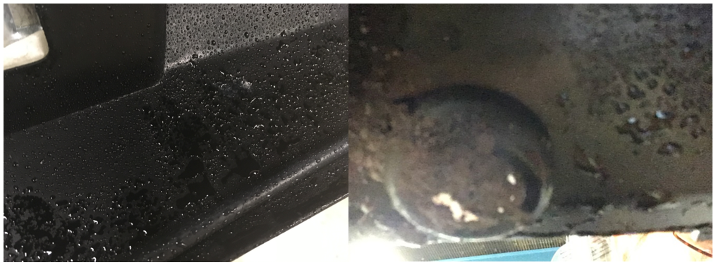
Ultrasonic transducers are inherently narrowband in their response, as they have a specific resonant frequency. However, wideband acoustical noise sources such as the white noise from air brakes may have significant content in the ultrasonic range of the transducer, which can be falsely perceived as an echo. Because the transducer must be exposed to the environment to function, it is also vulnerable to contamination by rain and mud, which can have a negative impact on the effectiveness of the sensing application. Figure 3 shows examples of water and mud on the sensors.
 Figure 3 Water on Capacitive Sensor, and Mud on Ultrasonic Sensor
Conclusion
You can use either capacitive or ultrasonic sensing to implement a hands-free kick-to-open feature for automotive applications. You should consider the relative strengths of each to determine which method best suits your needs.
Additional Resources:
- Check out these reference designs:
- Check out these evaluation modules:
IMPORTANT NOTICE AND DISCLAIMER
TI PROVIDES TECHNICAL AND RELIABILITY DATA (INCLUDING DATASHEETS), DESIGN RESOURCES (INCLUDING REFERENCE DESIGNS), APPLICATION OR OTHER DESIGN ADVICE, WEB TOOLS, SAFETY INFORMATION, AND OTHER RESOURCES “AS IS” AND WITH ALL FAULTS, AND DISCLAIMS ALL WARRANTIES, EXPRESS AND IMPLIED, INCLUDING WITHOUT LIMITATION ANY IMPLIED WARRANTIES OF MERCHANTABILITY, FITNESS FOR A PARTICULAR PURPOSE OR NON-INFRINGEMENT OF THIRD PARTY INTELLECTUAL PROPERTY RIGHTS.
These resources are intended for skilled developers designing with TI products. You are solely responsible for (1) selecting the appropriate TI products for your application, (2) designing, validating and testing your application, and (3) ensuring your application meets applicable standards, and any other safety, security, or other requirements. These resources are subject to change without notice. TI grants you permission to use these resources only for development of an application that uses the TI products described in the resource. Other reproduction and display of these resources is prohibited. No license is granted to any other TI intellectual property right or to any third party intellectual property right. TI disclaims responsibility for, and you will fully indemnify TI and its representatives against, any claims, damages, costs, losses, and liabilities arising out of your use of these resources.
TI’s products are provided subject to TI’s Terms of Sale (www.ti.com/legal/termsofsale.html) or other applicable terms available either on ti.com or provided in conjunction with such TI products. TI’s provision of these resources does not expand or otherwise alter TI’s applicable warranties or warranty disclaimers for TI products.
Mailing Address: Texas Instruments, Post Office Box 655303, Dallas, Texas 75265
Copyright © 2023, Texas Instruments Incorporated