-
How to Create Your Own Low-power Telemetry Logger for a Drone SSZTA12 July 2017 MSP430FR5969 , MSP430FR5994
How to Create Your Own Low-power Telemetry Logger for a Drone
Casey McCrea
What does it take to build a compact data logger to measure six axes of acceleration plus altitude for a hobbyist drone project? After a few weeks of design effort and some careful soldering, I have the answer: 1in2 of printed circuit board (PCB) space, a couple of microelectrical mechanical system (MEMS) sensors, an MSP430™ ferroelectric random access memory (FRAM) microcontroller (MCU) and ~5mW of active power.
My goal was to create a data-logger system, no larger than a coin-cell holder, that I could attach to a drone in order to measure inertial forces and flight altitude for later study. My first step was to select two highly integrated digital-output MEMS sensors that would provide data about the drone’s movement in real time. They would need to be available in small packages and meet a low-power budget while active in order to run from a CR2032 coin cell. I chose an inertial module, which combines both a 3-D accelerometer and 3-D gyroscope in a single 2.5mm-by-3mm package, and an altimeter, which takes pre-compensated altitude measurements in a 3mm-by-5mm footprint. To read and store the measured data rapidly and with minimal power consumption, I selected the 16MHz MSP430FR5969 FRAM MCU to be the brain of the board. With 64KB of unified variable and code space, this MCU can store large arrays of sensor data without the need for external memory.
The MCU communicates with both sensors on a single I2C bus to configure sampling parameters and read measurements. In order to program the board and read data back off the device after a session of flying, the board has two small three-pin Japan solderless terminal (JST) ports to bring out the universal asynchronous receiver transmitter (UART) and programming pins. I also included a couple of status light-emitting diodes (LEDs) that have a number of different uses, and a single push-button that you can repurpose as desired.
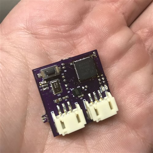
With the coin cell placed on the bottom of the PCB, I did most of the routing on the two-layer PCB on the top side, and accomplished everything in Eagle’s free schematic/layout suite. With a little bit of solder paste and a steady hand, I assembled the board (see Figure 1) and programmed the finished project in Code Composer Studio™ software. You can adjust the measurement frequency and bandwidth to suit accuracy, sampling rate and flight time (or for other applications).
 Figure 1 Telemetry Board Top
Side
Figure 1 Telemetry Board Top
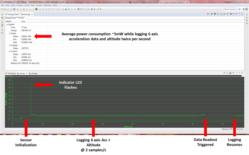
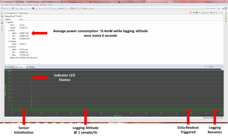
SideThe only remaining step was measuring the power consumption to estimate battery life. Using the MSP430 EnergyTrace™ software tool, I measured just ~5mW of total power at a rate of 14 measurements per second (see Figure 2). Reducing the measurement frequency to only one measurement every 4 seconds dropped the consumption to ~0.4mW, allowing for months of low-frequency data logging on a single coin-cell battery (see Figure 3).
 Figure 2 MSP430 EnergyTrace
Software with a Two-sample-per-second Measurement Frequency
 Figure 3 MSP430 EnergyTrace
Software with a One-sample-per-4-Second Measurement Frequency
Figure 3 MSP430 EnergyTrace
Software with a One-sample-per-4-Second Measurement FrequencyIn only a few short weeks of design, fabrication and coding, the project shaped up nicely and took its maiden voyage into the skies. What’s next for revision 2? With some additional memory space, I could really bump up the measurement frequency for the sensors. With the addition of GPS, I could track the drone’s location more accurately. Maybe the board could even find its way onto a skydiving trip! With a solid starting ground and ultra-low-power MSP430 hardware, the door is open to all sorts of creative hobbyist projects.