-
LDO Basics: Noise – How a Feed-forward Capacitor Improves System Performance
LDO Basics: Noise – How a Feed-forward Capacitor Improves System Performance
Aaron Paxton
This article was updated March 22, 2022 by Kyle Van Renterghem.
In the article, LDO basics: noise: – How a noise reduction pin improves system performance, I discussed how to lower output noise and control the slew rate by using a capacitor in parallel with the reference voltage (CNR/SS). For this article, let’s discuss another method to lower output noise: using a feed-forward capacitor (CFF).
What Is a Feed-forward Capacitor?
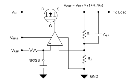
A feed-forward capacitor is an optional capacitor placed in parallel with the top resistor of the resistor divider, as shown in Figure 1.
 Figure 1 A Low-dropout Regulator (LDO) Using a Feed-forward Capacitor
Much like the noise-reduction capacitor (CNR/SS), adding a feed-forward capacitor has multiple effects. These effects include improved noise, stability, load response and the power-supply rejection ratio (PSRR). The application report, “Pros and Cons of Using a Feedforward Capacitor with a Low-Dropout Regulator,” covers these benefits extensively. It’s also worth noting that a feed-forward capacitor is only viable when using an adjustable LDO because the resistor network is external.
Improved Noise
As part of the voltage regulation control loop, the error amplifier of the LDO uses the resistor network (R1 and R2) to increase the gain of the reference voltage, similar to a noninverting amplifier circuit that drives the gate of the field-effect transistor so that VOUT = VREF × (1 + R1/R2). This increase means that the DC voltage of the reference will be gained up by a factor of 1 + R1/R2. Within the bandwidth of the error amplifier, the AC elements (such as noise) of the reference voltage are gained up as well.
By adding a capacitor across the top resistor (CFF), you are introducing an AC shunt for a particular range of frequencies. In other words, you are keeping the AC elements in that frequency range within unity gain. Keep in mind that the impedance properties of the capacitor you’re using will determine this frequency range.
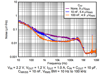
Figure 2 illustrates the reduction in noise of the TPS7A91 by using different CFF values.
 Figure 2 TPS7A91 Noise vs. Frequency and CFF Values
By adding a 100-nF capacitor across the top resistor, you can reduce the noise from 9 μVRMS to 4.9 μVRMS.
Improved Stability and Transient Response
Adding a CFF also introduces a zero (ZFF) and pole (PFF) into the LDO feedback loop, calculated with Equations 1 and 2:
ZFF = 1 / (2 × π × R1 × CFF) (1)
PFF = 1 / (2 × π × R1 // R2 × CFF) (2)
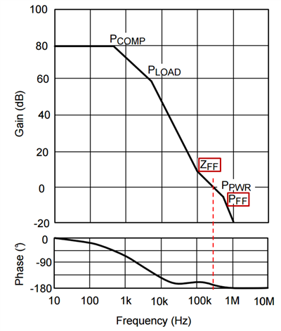
Placing the zero before the frequency where unity gain occurs improves the phase margin, as shown in Figure 3.
 Figure 3 Gain/phase Plot for a Typical LDO Using Only Feed-forward Compensation
You can see that without ZFF, unity gain would occur earlier, around 200 kHz. By adding the zero, the unity-gain frequency pushes a little to the right at approximately 300 kHz, but the phase margin also improves. Since PFF is to the right of the unity-gain frequency, its effect on the phase margin will be minimal.
The additional phase margin will be evident in the improved load transient response of the LDO. By adding phase margin, the LDO output will ring less and settle quicker.
Improved PSRR
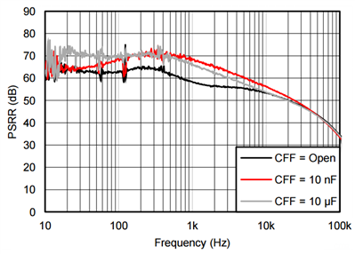
Depending on the placement of the zero and pole, you can also strategically lessen the gain rolloff. Figure 3 shows the effect of the zero on gain rolloff starting at 100 kHz. By increasing the gain in the frequency band, you will also improve the loop response for that band, which will lead to improvements in PSRR for that particular frequency range. See Figure 4.
 Figure 4 TPS7A8300 PSRR vs. Frequency and CFF Values
As you can see, increasing the CFF capacitance pushes the zero leftward, which will lead to a better loop response and corresponding PSRR at a lower frequency range.
Of course, you must choose the value of CFF and the corresponding placement of ZFF and PFF to avoid introducing instability. You can prevent instability by following the CFF limits prescribed in the data sheet, though TI generally recommends selecting a value between 10 nF and 100 nF. A large CFF can introduce other challenges outlined in the pros and cons application report mentioned earlier.
Table 1 lists some rules of thumb regarding how CNR and CFF affect noise.
| Parameter | Noise | ||
|---|---|---|---|
| Low frequency(<1kHz) | Mid frequency(1kHz-100kHz) | High frequency(>100kHz) | |
| Noise-reduction capacitor(CNR) | +++ | + | No effect |
| Feed-forward capacitor (CFF) | + | +++ | + |
Conclusion
Adding a feed-forward capacitor can lead to improvements in noise, stability, load response and PSRR. Of course, you must carefully select the capacitor to maintain stability. When coupled with a noise-reduction capacitor, it becomes possible to greatly improve AC performance. These are a just few tools to keep in mind for optimizing your power supply.
Additional Resources
- Read more LDO basics articles on topics such as thermals, capacitor vs. capacitance and preventing reverse current.
- Watch the “LDO Basics” video series for trainings about LDO dropout voltage, current limit, PSRR, noise and thermals.
- Read the Analog Applications Journal article, “LDO Noise Examined in Detail.”
- Check out the “Low Dropout Regulators Quick Reference Guide.”
- Learn how to actually make sensitive noise measurements in the white paper, “How to Measure LDO Noise."
IMPORTANT NOTICE AND DISCLAIMER
TI PROVIDES TECHNICAL AND RELIABILITY DATA (INCLUDING DATASHEETS), DESIGN RESOURCES (INCLUDING REFERENCE DESIGNS), APPLICATION OR OTHER DESIGN ADVICE, WEB TOOLS, SAFETY INFORMATION, AND OTHER RESOURCES “AS IS” AND WITH ALL FAULTS, AND DISCLAIMS ALL WARRANTIES, EXPRESS AND IMPLIED, INCLUDING WITHOUT LIMITATION ANY IMPLIED WARRANTIES OF MERCHANTABILITY, FITNESS FOR A PARTICULAR PURPOSE OR NON-INFRINGEMENT OF THIRD PARTY INTELLECTUAL PROPERTY RIGHTS.
These resources are intended for skilled developers designing with TI products. You are solely responsible for (1) selecting the appropriate TI products for your application, (2) designing, validating and testing your application, and (3) ensuring your application meets applicable standards, and any other safety, security, or other requirements. These resources are subject to change without notice. TI grants you permission to use these resources only for development of an application that uses the TI products described in the resource. Other reproduction and display of these resources is prohibited. No license is granted to any other TI intellectual property right or to any third party intellectual property right. TI disclaims responsibility for, and you will fully indemnify TI and its representatives against, any claims, damages, costs, losses, and liabilities arising out of your use of these resources.
TI’s products are provided subject to TI’s Terms of Sale (www.ti.com/legal/termsofsale.html) or other applicable terms available either on ti.com or provided in conjunction with such TI products. TI’s provision of these resources does not expand or otherwise alter TI’s applicable warranties or warranty disclaimers for TI products.
Mailing Address: Texas Instruments, Post Office Box 655303, Dallas, Texas 75265
Copyright © 2023, Texas Instruments Incorporated