SSZTA16 july 2019 ISO7731
All major countries are investing in the smart grid and are committed to making it a success. Why? Because power demand is going up, grid and power distribution will be critical. As demand increases, the cost of power increases because the resources to generate electricity are limited, resulting in huge growth in this segment). There are more than 900 million e-meters committed worldwide, with ~65% still to be deployed.
By definition, the smart grid means a bidirectional flow of energy and communication from generation to consumption (end to end). A smart meter is the key end equipment in this chain, which measures and sends power usage and supports automated billing, remote disconnection, time-of-use pricing models, and so on.
In this post, we will explain where you need isolation in a smart meter application.
Figure 1 shows an example smart meter, which includes a communication board that can have wired or wireless communication ports. The most commonly used wired communication interface used for meter-reading applications is RS-485. Here, isolation is required to break the ground potential difference between the energy meter and meter-reading node, which could be hundreds of meters away.
Certain e-meters have an RS-232 port to enable human operators to connect meter-reading equipment directly to the energy meter. In such cases, isolation is required to prevent electrical shock and any damage to meter-reading equipment from high-voltage surges that can appear on the AC mains.
 Figure 1 Typical Block Diagram of
Single Phase Smart E-Meter
Figure 1 Typical Block Diagram of
Single Phase Smart E-MeterIn polyphase smart electricity, shunt sensors are becoming more popular than current transformers (CTs) for phase current sensing. The main benefit of using a shunt sensor over a CT is that the measurement function becomes more immune to magnetic tampering. Thus, the trend globally is toward shunt-based polyphase smart e-meters.
Figure 2 shows a system that needs to sample voltage and current for each phase. To preserve phase-to-phase isolation, you can use either a metrology microcontroller (MCU) or a dedicated analog-to-digital converter (ADC) for each phase. Grid parameters are sent across the isolation barrier to the host MCU, which performs data aggregation and communication. Thus, an isolation device is required between the host MCU and metrology MCUs/ADCs.
 Figure 2 Typical Block Diagram of
Polyphase E-Meter
Figure 2 Typical Block Diagram of
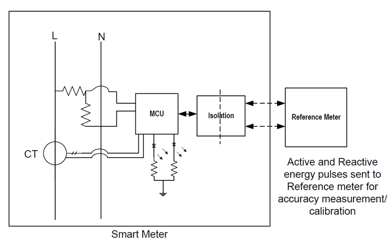
Polyphase E-MeterAnother use case for isolation in smart electricity meters is when testing the e-meter’s active and reactive energy accuracy by connecting a reference meter. The smart e-meter outputs pulses at a rate proportional to the amount of energy consumed by the load. A reference meter determines the accuracy of the smart e-meter by calculating the error based on these pulses.
An isolation device provides galvanic isolation between the smart e-meter and the reference meter, as shown in Figure 3.
 Figure 3 Block Diagram Showing Energy
Calibration in an E-Meter Design
Figure 3 Block Diagram Showing Energy
Calibration in an E-Meter DesignTrends in Smart E-Meters
According to recent industry reports, distribution utilities globally are expected to spend approximately $378 billion on smart grid technologies by 2030. No doubt, intelligent smart e-meters are going to be the trend in the future, where two-way communication will help consumers and utilities connect with each other more effectively. But at the same time, there will be an increased emphasis on higher safety standards and reliable data communication.
Optocouplers have traditionally provided isolation for many years, but with the industry’s move toward an advanced metering infrastructure, there is a need for higher isolation rating (4 KVrms or higher) and support for higher data rate with lower power consumption.
E-meter standards in some countries mandate that the meter remain in service for a much longer period of time; thus, maintaining effective isolation over a period of 15 years or more is important. Aging effects in light-emitting diode (LED)-based optocouplers often limit their lifetimes to less than 10 years. So it becomes imperative that you choose an alternate isolation barrier that is more reliable and lasts for more than 15 years.
Our ISO77xx family of digital isolators, such as the ISO7731, are high-performance reinforced 5-KVrms digital isolators. TI’s isolators use silicon dioxide (SiO2) as dielectric material, which has high breakdown strength (500 V/µm to 800 V/µm). These capacitive isolators are immune to moisture and temperature and can last for more than 100 years. They isolate complementary metal-oxide semiconductor (CMOS) digital input/outputs (I/Os), provide high electromagnetic immunity, are very low in radiated emissions and consume very low power.
The inherent architecture of optical isolators limits the data rates to few kilobits per second, whereas TI capacitive isolators can handle data rates as high as 100 Mbps. There are high-speed optocouplers in the market, but as the speed goes above 1 Mbps, they start to become expensive. Plus, there are few high-speed optocouplers available in more than two channels in a single package, whereas TI capacitive isolators are available with as many as six channels in a single 16-pin small-outline integrated circuit (SOIC) package. As the number of isolation channels in a system increases, the low-cost solution advantage of optocouplers starts to diminish, because an integrated multichannel digital isolator requires fewer external components and occupies much less board space.
For these reasons, digital isolators are preferable to optocouplers for smart e-meters.
Additional Resources
- Choose the right digital isolator for your smart e-meter.
- Check out these reference designs: