Power Tips: A Simple Circuit to Implement Smooth Soft Start for an Isolated Converter
Most DC/DC converters require a soft-start circuit to limit the in-rush current at startup. Although a smooth soft start is required for systems with power-on reset (POR), this is difficult for an isolated converter with a controller on the primary side and a limited duty cycle or current.
Figure 1 shows the soft start of a forward converter with a duty-cycle soft start from the primary side. The steady-state output of the converter is 12V. A 50% load current is applied at 10V, the POR threshold of the system. As soon as a load is applied, the output drops and triggers system shutdown, causing the system power cycle several times. At the end of soft start, the output overshoots 10%, which is not desirable.
 Figure 1 Output of a Forward Converter
During Startup with a Load Applied at 10V
Figure 1 Output of a Forward Converter
During Startup with a Load Applied at 10VIn this post, I will use a simple circuit to achieve a smooth soft start for an isolated converter. The circuit is applied to an active-clamp forward converter with the LM5025 as the controller. Figure 2 shows the concept of secondary-side soft start.
 Figure 2 Secondary-side Soft-start
Circuit for an Isolated Converter
Figure 2 Secondary-side Soft-start
Circuit for an Isolated ConverterWhen first applying the input, the converter output (VOUT) starts to rise. The capacitor (CSS) is charging up. The CSS charging current (ISS) flows through the resistor (RSS). When ISS is high, then VBE(on)/RSS. QSS turns on and starts to pull current from the secondary-side comp node (SEC COMP), thus reducing the duty cycle. During soft start, the error amplifier saturates and the soft-start circuit dominates the feedback loop. The converter, CSS, RSS, QSS and optocoupler form a closed loop. When the output rises to regulation, the error amplifier starts to regulate and ISS reduces. QSS turns off.
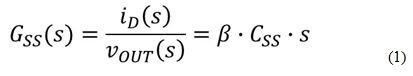
Equation 1 shows the transfer function from VOUT to the optocoupler current:
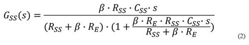
While being effective, this simple circuit might not be stable because the QSS forward gain (β) is high and varies dramatically from part to part. To stabilize this circuit, insert a gain-reducing resistor (RE) between the emitter of QSS and ground, as shown in Figure 3. Increasing RE can reduce the feedback-loop gain during startup.
 Figure 3 Adding RE To
Stabilize the Soft-start Circuit
Figure 3 Adding RE To
Stabilize the Soft-start CircuitEquation 2 shows the soft-start circuit transfer function with RE:
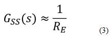
At high frequencies, use Equation 3 as an approximation of Equation 2:
I added the soft-start circuit to the converter with these parameters:
- CSS = 0.1µF.
- RSS = 100kΩ.
- RE = 1.18kΩ.
Figure 4 shows the soft-start waveform with these circuit parameters. When the system starts pulling current, the soft-start circuit stops drawing current from the COMP and the duty cycle increases quickly. The converter continues to soft start, after a minor dip caused by the load transient.
 Figure 4 Soft-start Waveform of the
Soft-start Circuit Shown in Figure 3
Figure 4 Soft-start Waveform of the
Soft-start Circuit Shown in Figure 3Figure 4 also shows that after the load is applied, the converter switching node (VSW) has an additional voltage spike. Figure 5 shows the zoomed-in waveform. It is obvious that the system oscillates at 9.5kHz.
 Figure 5 Zoomed-in Soft-start Waveform
with Soft-start Circuit
Figure 5 Zoomed-in Soft-start Waveform
with Soft-start CircuitThe controller in this design is a voltage-mode controller. The power stage has 180 degrees of phase drop because of the double poles. It is necessary to add a zero to improve stability; you can do this by adding a capacitor (CE), in parallel to RE. In order to add 45 degrees to the phase margin, I placed a zero at 9.5kHz, the measured oscillation frequency. With RE = 1.18kΩ, I added a 15nF capacitor.
 Figure 6 Soft-start Circuit with
Improved Stability
Figure 6 Soft-start Circuit with
Improved StabilityFigure 7 shows the startup waveform with CE = 15nF. The oscillation is eliminated. The total soft-start time is 50ms.
 Figure 7 Soft-start Waveform with
CE = 15nF
Figure 7 Soft-start Waveform with
CE = 15nFDuring soft start, the typical optocoupler diode current (Iopto_D) is from 1.2mA to 0.8mA. This is determined by the LM5025 and the optocoupler forward gain. With RE = 1.18kΩ, the voltage across RSS is VBE(ON) + RE × 0.8mA = 1.644V. VBE(on) = 0.7V. Thus, you can calculate ISS as ISS = (VBE(ON) + RE × Iopto_D)/RSS. ISS/CSS sets the output VOUT, dv/dt. To ensured the effectiveness of the secondary-side soft-start, the primiary-side soft-start should be set much faster than the secondary-side soft-start as well.
Test results show the effectiveness of this simple soft-start circuit to achieve a smooth soft start for an isolated converter.
Additional Resources
- Read more Power Tips blogs.
- Watch Power Tips videos.
- Download the LM5025 data sheet.
IMPORTANT NOTICE AND DISCLAIMER
TI PROVIDES TECHNICAL AND RELIABILITY DATA (INCLUDING DATASHEETS), DESIGN RESOURCES (INCLUDING REFERENCE DESIGNS), APPLICATION OR OTHER DESIGN ADVICE, WEB TOOLS, SAFETY INFORMATION, AND OTHER RESOURCES “AS IS” AND WITH ALL FAULTS, AND DISCLAIMS ALL WARRANTIES, EXPRESS AND IMPLIED, INCLUDING WITHOUT LIMITATION ANY IMPLIED WARRANTIES OF MERCHANTABILITY, FITNESS FOR A PARTICULAR PURPOSE OR NON-INFRINGEMENT OF THIRD PARTY INTELLECTUAL PROPERTY RIGHTS.
These resources are intended for skilled developers designing with TI products. You are solely responsible for (1) selecting the appropriate TI products for your application, (2) designing, validating and testing your application, and (3) ensuring your application meets applicable standards, and any other safety, security, or other requirements. These resources are subject to change without notice. TI grants you permission to use these resources only for development of an application that uses the TI products described in the resource. Other reproduction and display of these resources is prohibited. No license is granted to any other TI intellectual property right or to any third party intellectual property right. TI disclaims responsibility for, and you will fully indemnify TI and its representatives against, any claims, damages, costs, losses, and liabilities arising out of your use of these resources.
TI’s products are provided subject to TI’s Terms of Sale (www.ti.com/legal/termsofsale.html) or other applicable terms available either on ti.com or provided in conjunction with such TI products. TI’s provision of these resources does not expand or otherwise alter TI’s applicable warranties or warranty disclaimers for TI products.
Mailing Address: Texas Instruments, Post Office Box 655303, Dallas, Texas 75265
Copyright © 2023, Texas Instruments Incorporated