SSZTAE6 february 2017 TPS23861
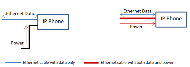
Power over Ethernet (PoE) enables Ethernet cables to carry electrical power as well as data. For example, old Internet protocol (IP) phones usually needed a DC power supply and Ethernet cable to deliver power and data, respectively. With PoE implemented in an Ethernet switch, power is delivered through the Ethernet cable to the IP phone, eliminating the need for a power supply. See Figure 1.
 Figure 1 Old & New IP Phone Data/power Path
There are two types of devices on both sides of an Ethernet cable: power sourcing equipment (PSE) and powered device (PD). On the sourcing side, PSE devices are usually installed in Ethernet switches, routers, gateways and wireless backhauls. PDs manage and protect the PoE system at the load side. PDs are usually installed in IP phones, security cameras and access points.
In this post, I will explain when you need system software to control PSE in order to implement more functionalities than what’s defined in IEEE802.3at(Institute of Electrical and Electronics Engineers standard for Ethernet), and how to get started with TPS23861 PoE MSP430™ microcontroller (MCU) reference code to develop your own system software.
The TPS23861, a PoE PSE controller, is one of the most popular PSE devices available for mass-market applications, designed in products such as Surveillance NVRs, Ethernet switches and wireless access points. It comes with three modes: auto mode, semi-auto mode and manual mode. In auto mode, host control is not necessary and the TPS23861 can operate by itself (including detection, classification, power on and fault handling). This mode is usually used in standard low-port-count PSE systems. In semi-auto mode, the port automatically performs detection and classification as long as the detection and classification are enabled (0x14). A push-button command (0x19h) is required to power on the port. Semi-auto mode is usually used in high-port-count PSE systems that designers can implement multiport power management. Manual mode provides the most flexibility. It is used in nonstandard PoE applications such as high-power PoE PDs and non-PoE loads.
When operating in semi-auto or manual mode, systems with these criteria will need an external MCU to control the PSE:
- The system has a high port count (more than eight ports).
- The system needs to connect to nonstandard PDs such as high-power PoE PDs.
- The power supply is not able to provide power to all ports with full loads, so a multiport power-management module is necessary.
Once you determine whether your system requires an external MCU, a good resource to use to develop your own software is the TPS23861 PoE MSP430 MCU reference code. This system software supports:
- Full compliance to the IEEE802.3at PoE specification.
- Device detection, classification and power on.
- Fault reporting (overcurrent, overtemperature, DC disconnect, etc.).
- Multiport power management.
Multiport Power Management
The maximum system power available limits the total number of powerable ports. For example, each PoE PD can draw a maximum of 30W, and a 48-port system can draw more than 1,440W of total system power. If the maximum system power available is less than 1,440W, multiport power management then becomes necessary so that the available system power may be used most efficiently while meeting the goals.
In the TPS23861 PoE MSP430 MCU reference code, a multiport power-management module is implemented in semi-auto mode reference code.
There two approaches to implementing the power-management feature:
- Powering on each port without checking the remaining power and turning off ports if the total system power exceeds the power budget.
- Before powering on each port, calculating the total system power and checking if the remaining power is enough to power on the port or not.
The TPS23861 PoE MSP430 MCU reference code implements the second approach, considering more severe cases when the margin between the power budget in the software and the actual power capability of the power supply is not enough to turn on one extra port.
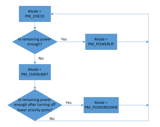
The multiport power-management module is inserted after the PSE discovers a valid PoE PD. My initial thought was to calculate how much power was left and compare it to the power that the current port is requesting (estimated by the class result after classification). If the remaining power is enough to turn on the current port, it will then initiate the power-on command; otherwise, the system software or host will check if there’s any ports powered on with lower priority. When a PD device connects to the PSE port, the PSE generates an interrupt; then the host knows which port is connected with a PD.
If there is a lower-priority port, the host will power off the port in order to have enough power to turn on the current port.
If you think more deeply about it, you will find that there are some corner cases that haven’t been considered in the above logic:
- What if after turning off all lower-priority ports, the remaining power is still not enough to turn on the current port?
- Since system power is only calculated when a port is inserted and finishes classification, what if the PD has a sleep mode or doesn’t pull a full load after power on, and at a certain time the load suddenly increases?
Taking these two corner cases into consideration, we optimized the multiport power management algorithm in two ways:
- Instead of turning off a lower-priority port after recognizing insufficient power, we first check whether the remaining power is sufficient after turning off all ports that have lower priority than the current port. If the power is still not sufficient, we just leave the current port waiting. Otherwise we turn off the lowest-priority port in each loop.
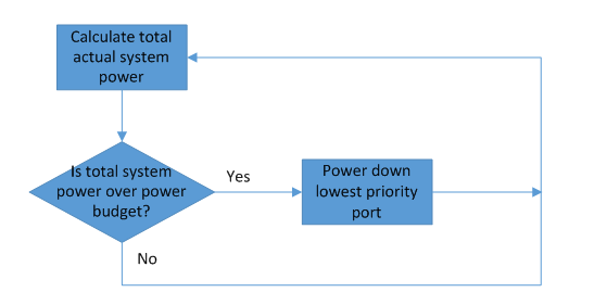
- To avoid having a load-step change damage the power supply, we added a module running in a timer-triggered interrupt that monitors the total consumed system power. If it exceeds the power budget, it will turn off the lowest-priority port.
Figure 2 shows the flow chart of power on decision and Figure 3 shows the system power monitor flow chart.
 Figure 2 Power-on Decision Flow
Chart
 Figure 3 System Power Monitor Flow
Chart
Figure 3 System Power Monitor Flow
ChartTI provides TPS23861 PoE MSP430 MCU reference code to help designers ramp up quickly and develop software without having to develop it from scratch. Customers can take this code to an MSP430 MCU LaunchPad™ development kit and run it with the TPS23861EVM. For more information on the TPS23861EVM, see the EVM user guide for instructions and software architecture.
Additional Resources
- Learn more about the TPS23861 PSE controller in combination with TPS23861 PoE the MSP430 MCU reference code for power port management in this training: TPS23861 PoE MSP430 Reference Code Training
- Download the TPS23861 PoE MSP430 MCU reference code.
- See common PoE FAQs.