SSZTAL7 november 2016
Capacitors are an essential component of a synchronous buck converter. There’s a variety of capacitor technologies so it’s important to know what parameter of the input and output capacitors you need to consider when designing a synchronous buck converter as shown in Figure 1.
 Figure 1 Synchronous Buck DC/DC
Converter
Figure 1 Synchronous Buck DC/DC
ConverterPower capacitors selection considerations are shown in the Table 1 below:
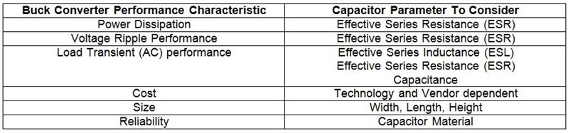 |
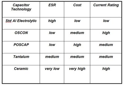
Table 2 below shows the relative capacitor characteristics depending on the technology.
 |
Capacitor impedance over frequency is also important as it determines the buck converter switching frequency at which the capacitor acts as a capacitor for energy storage, and not as an inductor. Impedance can be due to the ESR (Effective Series Resistance) and ESL (Effective Series Inductance) of a capacitor and it looks like a U-shaped curve as shown in Figure 2. The Self-Resonant Frequency, also shown in Figure 2, is the frequency after which the capacitor starts to look like an inductor (example shown for the 10uF capacitor). Ideally, we want the buck converter to switch at a switching frequency in the capacitor region.
We can use combinations of capacitors to “flatten” the impedance curve with the objective to push the buck converter switching frequency higher while still operating in the capacitive region. Capacitor impedance varies by technology and switching frequency.
 Figure 2 Capacitor Impedance over
Switching Frequency
Figure 2 Capacitor Impedance over
Switching FrequencySo, how do you choose a capacitor for an input and output filter?
For an input filter you choose a capacitor to handle the input AC current (ripple) and input voltage ripple.
For an output filter you choose a capacitor to handle the load transients and to minimize the output voltage ripple.
The equation in Figure 3 shows the equation to determine the input current RMS (Root-Mean-Squared) current the capacitor can handle. Based on the input voltage, the input current RMS current, and the input voltage peak-to-peak ripple you can choose the capacitor looking at the capacitor datasheets. It is recommended to use a combination of Aluminum Electrolytic (AlEl) and ceramic capacitors. Ceramic capacitors have low ESR and they can reduce the input voltage peak-to-peak ripple, which, in turn, reduces the input ripple current for the input bulk capacitors to handle.
 Figure 3 Input Capacitor RMS Current
Calculation
Figure 3 Input Capacitor RMS Current
CalculationWhen considering output capacitors, Table 3 below shows the selection criteria:
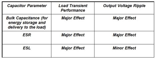 |
Figure 4 below shows how each Output Capacitor Component can affect the buck converter load transient performance.
 Figure 4 Capacitor Criteria in Load
Transient Performance
Figure 4 Capacitor Criteria in Load
Transient PerformanceCapacitor calculations for the output voltage overshoot, undershoot, and peak-to-peak voltage ripple are used to determine the capacitance as shown in Figure 5 and Figure 6 below.
 Figure 5 Determining Output Capacitance
for Output Voltage Undershoot and Overshoot
Figure 5 Determining Output Capacitance
for Output Voltage Undershoot and Overshoot Figure 6 Determining Output Capacitance
for Output Voltage Peak-to-peak Ripple Handling
Figure 6 Determining Output Capacitance
for Output Voltage Peak-to-peak Ripple HandlingAn example for selecting an output capacitor is shown below:
Output Capacitor Selection Example:
- 2A to 10A load step @ 15A/ms
- Use 2x 1000 mF Aluminum.
Elco: 19mW ESR
- PLOSS = (3.32/2)2 x 19/2 x 10-3 = 0.024W]
- To help reduce spikes, add two 10 mF ceramics (1210), 0.8mW ESR , 1.1nH ESL each
- This selection yields:
- 1.7mV output voltage undershoot
- 10.7mV output voltage overshoot
- 19.9mV voltage spikes
- 2.8mV of output voltage peak-to-peak ripple
So, when designing a buck converter keep these capacitor selection criteria in mind for a high-performance, stable and reliable design! Consider one of TI’s buck converters and buck controllers for your next DC/DC power supply design.