SSZTB09 August 2016 TPS51622
Multilayer ceramic capacitors (MLCCs) are popular in power electronics designs compared to traditional polymer capacitors for many reasons:
An MLCC provides:
- A small profile with relatively higher capacitance.
- Very low equivalent series resistance (ESR).
- Very low equivalent series inductance (ESL).
- Lower impedance at higher frequencies.
- Non-polarization for easier mounting and manufacturing.
- Higher reliability over time compared to tantalum and aluminum electrolyte capacitors.
- Lower unit costs.
However, MLCCs do not always sit quietly on the board and do their job. Sometimes they get bored and start to “sing.” This is due to the piezoelectric effect of the ceramic material, which has the same characteristics as other ferroelectric dielectrics. When an electric potential or field applied on the surface of an MLCC causes a deformation at a frequency range from 20Hz-20kHz, it could be audible to humans. This is called MLCC acoustic noise, or singing noise.
Major contributions to acoustic noise include:
- Electric potential operating at a frequency within an audible range.
- Smaller case size tends to be lower sound levels than lager case size.
- Ceramic dielectric constants (K); a higher K has higher ferroelectric properties.
- Less ceramic layers producing lower sound levels due to less deformation.
 Figure 1 MLCC and Board Deformation
When Applying an Electric Field
Figure 1 MLCC and Board Deformation
When Applying an Electric FieldThe MLCC itself should be quiet to human ears. However, it can be loud when mounted on a printed circuit board (PCB). Let’s say you had a ceramic capacitor at the input of a switching power converter. The switching behavior creates a high-frequency voltage change on the ceramic capacitor; as the voltage increases and decreases, the MLCC will expand and contract. The deformation of the MLCC creates vibration of PCB, which causes to buzz amplifying. The higher the electric potential change, the larger the deformation (piezoelectric effect), which will result in a louder sound when the frequency occurs in the audible range.
Some applications can use electrolyte or tantalum-type capacitors, preferably thru-hole types when acoustic noise is problematic. But for applications that are more cost-sensitive or size-constrained (such as personal electronic devices), you cannot avoid thin, small ceramic capacitors, and the need to reduce noise immediately becomes critical.
Here are a few available solutions that can minimize or reduce noise to acceptable levels:
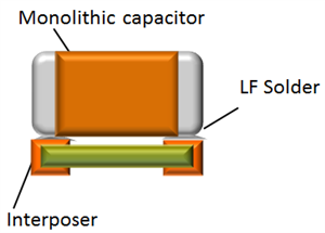
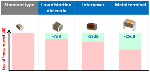
- Use acoustically quieter capacitors. Capacitor manufactures have already developed ceramic capacitors with low distortion dielectric material, which exhibit lower ferroelectric properties and smaller deformation in regards to a voltage change. And there is a series manufactured by Murata that the capacitor is on interposer substrate to reduce the acoustic noise (Figure 2). Murata also has a series with a special mechanical configuration; it uses metal terminals to mount the capacitor on the PCB board to achieve noise reduction by absorbing mechanical impact (Figure 3). Unfortunately, this kind of capacitor tends to be more expensive, which prevents its wide use by end-equipment manufacturers. The effect of noise suppression depends on the type of capacitors. (Figure 4)
 Figure 2 Mechanical Configuration
of “Interposer” Ceramic Capacitors
 Figure 3 Mechanical Configuration
of “Metal Terminal” Ceramic Capacitors
 Figure 4 Acoustic Noise Reduction
Effect by Each Capacitor (Typical Value)
Figure 4 Acoustic Noise Reduction
Effect by Each Capacitor (Typical Value)- Reducing noise by
optimizing PCB layout. The origin of the noise is the interaction of
MLCCs with the PCB. Optimizing component placement on the PCB can be
effective. Using a thicker PCB allows the sound frequency to shift due to
weight change. Some articles also suggest placing the components at the edge
of the PCB to lower the sound pressure level. Similarly, placing components
symmetrically on top and bottom of the PCB can also help to reduce noise
level, since the two vibrations will cancel each other out, due to the
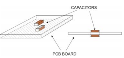
cancellation-of-vibration effect (Figure 5) when the voltage applies to both capacitors
simultaneously.
 Figure 5 Capacitors on Each
Side of a PCB to Create Vibration Cancellation
 - Reducing voltage amplitude variation on capacitors. In most cases, end device manufacturing is limited by cost or size, which makes the first two methods described to reduce acoustic noise not practical. However, the other main factor that determines noise is how high or fast the voltage variation is across the capacitors. This is something that can be optimized through proper system design, by either improving the load-transient response or line-transient response.
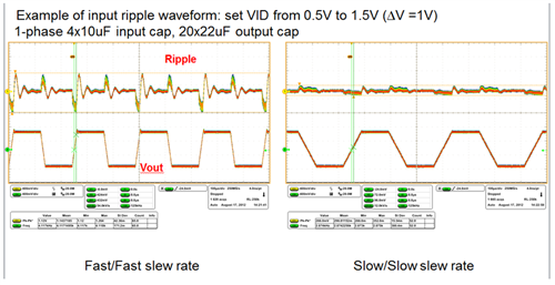
Considering line-transient response as an example, an experiment was conducted using the TPS51622, one of TI’s DCAP+™ Vcore controllers, by measuring the noise level with a sound meter when varying the output voltage change with fast (48mV/µs) and slow (12mV/µs) slew rates using the Intel voltage regulator (VR) tool. Sending an I2C command to the TPS51622 changes the output voltage from 0.5V to 1.5V, and the input-voltage ripple was measured shown in Figure 5.
 Figure 6 Input-voltage Ripple on Input
Ceramic Capacitors with Fast/slow Slew Rates
Figure 6 Input-voltage Ripple on Input
Ceramic Capacitors with Fast/slow Slew RatesThe voltage amplitude with a fast slew rate is much higher than with a slow slew rate; this voltage difference across the capacitor directly translates into an increase of noise in decibels. Measured data shows that the noise dropped to a lower, quieter level, from ~40dB to ~50dB. See table 1 for other sound levels and effects.

|
The wide usage of conventional ceramic capacitors brings acoustic noise issues to power system designs. However, there are solutions that approach the problem from different angles: changing the electronic characteristics of the MLCC itself, or minimizing its interaction with the PCB. These methods either reduce the noise to an acceptable level or remove the noise from the source by using more expensive “anti-noise” capacitors.