SSZTBP1 january 2016
High-voltage capacitive energy storage often provides power to repetitive high-power pulse loads such as a camera flash or radio transmitter. Storage capacitors supply a brief, high-power burst of energy to the load, but are then allowed to slowly recharge over a much longer time period. Their benefits generally include a lower average input current, which eases the requirements on the input source and reduces the size of the converter’s power stage. But storage capacitors can be quite large, so it’s beneficial to accurately determine the capacitance necessary in order to minimize their size. Let’s take a look at how to determine the required amount of capacitance.
The load discharging the storage capacitors can be categorized into three types: constant power, constant current or resistive. Figure 1 shows an example of how each type discharges a stand-alone 3400µF capacitor charged to 32V with an initial load of 69W. The constant power load, equivalent to that of a switching regulator, increases its current draw as the capacitor voltage decreases, further accelerating the voltage decay. To make things worse, the switching regulator’s efficiency also has an impact on the discharge rate. Converters such as boosts generally have lower efficiency as their input voltage decreases, drawing even higher power. Constant power is the most severe of the three types, requiring the most capacitance.
 Figure 1 Storage Capacitor Discharge
Rates
Figure 1 Storage Capacitor Discharge
RatesA constant current load provides a linear discharge slope. This makes predicting the capacitor’s “end” voltage relatively easy. The power drawn from the storage capacitor decreases as its voltage decreases and only certain types of loads have these characteristics. Examples of constant current loads include integrated circuits or applications such as a constant current LED driver, whose current is regulated by a linear regulator.
A resistive load has an exponentially decaying voltage and the longest holdup. A resistive load type is the least common of the three. Examples include an incandescent bulb, heating element or active load.
Once you know the load type, you can
use Equations 1, 2 and 3 to determine the necessary storage capacitance for a given
holdup time. Based on the curve in Figure 1, a constant-power load such as a 12V buck regulator could
operate for about 21ms before falling out of regulation. Alternatively, a constant
current load could support at least 16V for 25mS before requiring a recharge. If you
require a regulator to supply a fixed output voltage, be sure to factor in its
efficiency, as it will shorten the holdup time. Equations 1, 2 and 3 are: 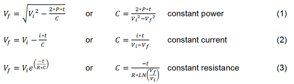
where
- Vf is the final capacitor voltage after time
- Vi is the initial capacitor voltage
- t is the discharge time
- i is the load current
- C is the storage capacitance
- P is the power
- R is the resistance.
Energy storage with a repetitive pulse load requires an understanding of the load type and its impact on the storage capacitor discharge rate. This allows you to select the proper capacitor bank size to achieve the necessary timing. High-voltage capacitive storage provides an effective method to supply a large, short-duration energy pulse.
Additional Resources
- See the EETimes Power Tips post "Dual-Loop Capacitor Energy Storage Circuit Powers Pulse Loads”
- For similar example designs, see Last Gasp Hold Up Energy Storage Solution and ATCA High Voltage Energy Storage Technique.