SSZTBQ0 january 2016 LM43602-Q1 , LP5907 , LP5907-Q1

Rearview cameras are becoming a fundamental safety feature for vehicles; in fact, the National Highway Safety Transportation Agency (NHTSA) announced that all cars built after May 2018 must have rear-visibility technology. So in this post, I will discuss the benefits of using low-dropout regulators (LDOs) to handle the power constraints of rearview cameras. Figure 1 shows common features of performance LDOs.
 Figure 1 LP5907 and LP5907-Q1
Features
Figure 1 LP5907 and LP5907-Q1
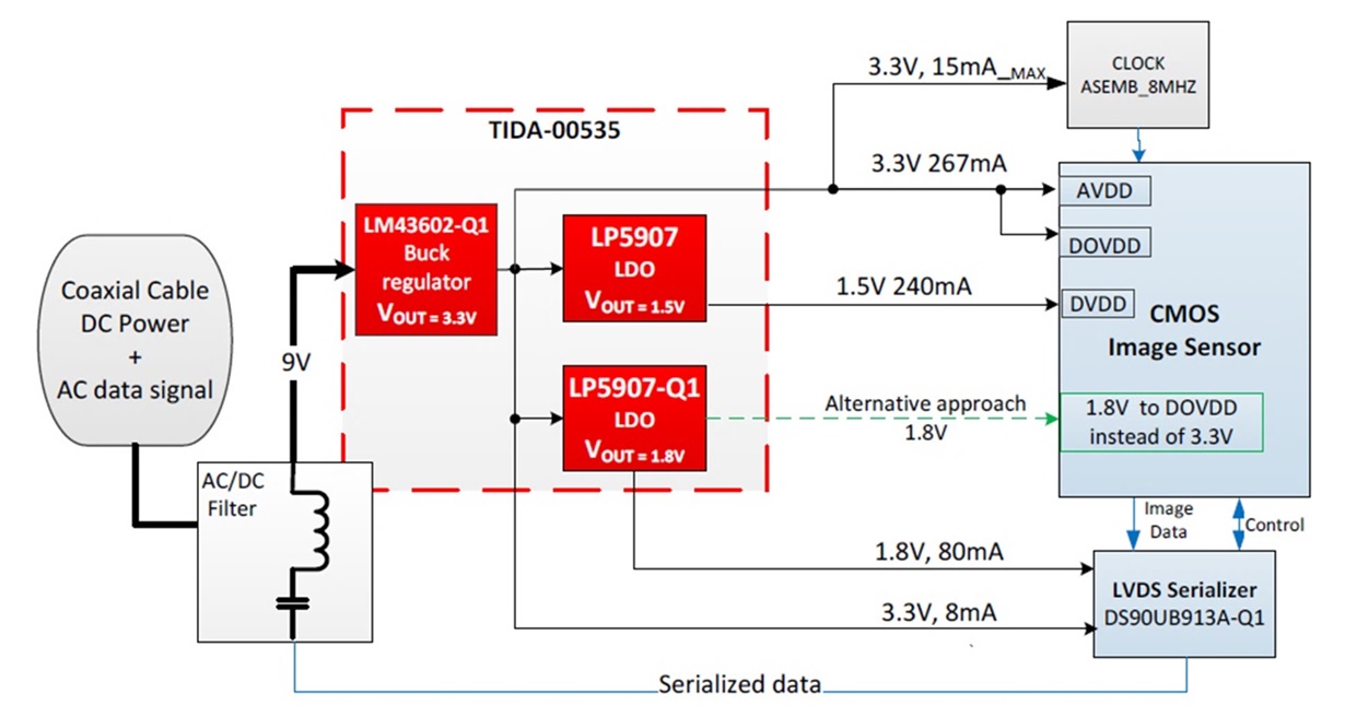
FeaturesIf you are designing a power supply for automobile cameras, your main concerns are clean voltage regulation and optimized total system size and cost. These requirements can be achieved using LDOs as shown in the TIDA-00535 reference design; TIDA-00535 provides guidelines, test data and design files of a power management solution at the camera module side. Figure 2 shows a conceptual block diagram of TIDA-00535.
 Figure 2 TIDA-00535 Block Diagram
Clean voltage regulation means low ripple and steady voltage regulation, both crucial for the Complementary Metal Oxide Semiconductor (CMOS) image sensor inside the camera module. The CMOS image sensor is sensitive to variations in the nominal input-voltage level. Voltage ripple and voltage undershoot and overshoot transients disturb the functionality of the active amplifier and photodetector element inside of the sensor, therefore the ability of the CMOS image sensor to capture incident light intensity is compromised, this means that the image quality will be affected presenting dots or dark lines across the image. With high power-supply ripple rejection (PSRR), low noise and great transient-response characteristics, LDOs are capable of minimizing the ripple voltage from a switching regulator or coupled interference in long PCB traces.
Image sensors require various voltage rails. One rail is usually between 2.8V and 3.3V, while the other rail requires lower voltages typically from 1.2V to 1.8V. The low-voltage rails are more sensitive to power-supply ripple; therefore high-PSRR LDOs are preferable. The LP5907-Q1 offers high-ripple rejection as shown in Figure 3.
 Figure 3 LP5907-Q1 Frequency vs. PSRR Graph
TIDA-00535 uses the LM43602-Q1 a switching-mode regulator to generate 3.3V from the power-over-coaxial source. The 3.3V voltage is further regulated using two LP5907-Q1 LDOs to generate 1.5 V and 1.8 V voltage rail. The LM43602-Q1 switches at a frequency of 500 KHz its output ripple is almost non-existing at the output of the LDOs thanks to the ~45 dB PSRR at 500 KHz. Figure 4 shows the ripple rejection capability of the LP5907-Q1 in an extreme case in which the LP5907-Q1 input voltage has a ripple of 50mVp-p at a frequency of 3 MHz.
 Figure 4 Comparison between Input
Voltage Ripple and LP5907 Regulated Output
Figure 4 Comparison between Input
Voltage Ripple and LP5907 Regulated OutputCameras should not affect the cosmetic design of the automobile; in other words, they should be small and somewhat concealed. Since camera modules have size constraints, a common practice is to transfer power and data between the engine control unit (ECU) and camera module with a coaxial cable or differential pair, minimizing the number of cables and components needed at the camera module location. LDOs help achieve total-solution-size and system cost requirements because they only need a few compensation components. For example, the LP5907-Q1 only needs a small input and output ceramic capacitor for stability, in contrary to switching regulators that requires capacitors, inductors and resistors increasing the total BOM cost and system size. In addition LP5907-Q1 is available in the Small Outline Transistor (SOT-23) package (2.90 mm by 1.60 mm) for automotive grade devices that needs to meet the Automotive Grade Council standards (AEC-Q100) and for non AEC-Q100 grade applications the LP5907 is available in smaller packages the Die-Sized Ball Grid Array (DSBGA) package which is only 0.675 mm by 0.675 mm (Max) and the Small Outline No-leads (X2SON) package 1.00 mm x 1.00 mm (NOM).
Efficiency might be another system concern. The system will only operate a few seconds at a time and most of the time it will be powered off by a relay at the ECU side, for these reasons the efficiency of the LDOs can be justify with its low noise and high PSRR performance.
To summarize, LDOs can greately contribute to automobile camera’s power management by providing a high PSRR and low noise output while mantaining a small total solution size at an optimized BOM cost.
To get started review the Power Management Solution for Automotive CMOS Imager and Data Serializer Reference Design which provides a detail design guide, schematics, Gerber files and a bill of materials for the power section of a camera module.
Additional Resources:
- Small Size, low noise and High PSRR Power Reference Design for CMOS Image Sensors
- View rear camera reference designs and solutions.
- Download the “Advanced Driver Assistance (ADAS) Solutions Guide” and “Automotive and Transportation Solutions Guide.”
- Read another blog about power supply design considerations for advanced driver assistance systems.