Has Distortion Got Your Amplifier Down? Get More Bandwidth!
When excessive harmonic distortion appears in the output of an amplifier and you can’t find the source of the distortion in the obvious places, insufficient bandwidth is the next place to look.
Typically, the closed-loop bandwidth of the amplifier should be at least 10 times the highest frequency of the signal for acceptable harmonic distortion. Why is that?
Consider the noninverting operational-amplifier (op-amp) circuit in Figure 1.
 Figure 1 Noninverting Op-amp
Circuit
Figure 1 Noninverting Op-amp
CircuitAssume that the op amp has one input gain stage with gain A1 and an output stage with a gain A2 ≈ 1. Figure 2 shows a model of the op-amp circuit in Figure 1 with ei as the distortion added by each internal stage of the op amp. Note that the distortion is referred to the output of each stage, since that is where it physically appears with its full magnitude.
 Figure 2 Distortion Model of Op-amp
Circuit
Figure 2 Distortion Model of Op-amp
Circuit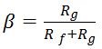 is the feedback factor, or the fraction of the output
fed back to the inverting input.
is the feedback factor, or the fraction of the output
fed back to the inverting input. Each distortion term will appear in the output, Vout, with a different attenuation. Why is the distortion attenuated in the output and not amplified by the various gain stages in the amplifier? A fraction, β, of the distortion in Vout is fed back to the negative op-amp input, so it is inverted by the op-amp input stage. This inverted fractional distortion is amplified by all of the gain stages prior to the original source of the distortion. The amplified and inverted fractional distortion is then added to the original distortion. Because the distortion fed back is inverted at the negative input, the feedback reduces distortion in the output.
At higher frequencies, the inverted feedback will acquire a phase shift through each gain stage so that it will not be inverted (that is, 180 degrees out of phase with the original distortion) and the attenuation of each distortion source will be reduced. Near DC, the phase shift is negligible, so you can do a simple algebraic analysis of the attenuation for each distortion source.
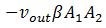
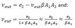
To calculate the distortion in Vout due to the distortion, e1, of the first gain stage, use superposition to set Vin and the other distortion sources to zero.
The equation for Vout then becomes:
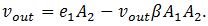
Where the second term
 is the fractional output inverted and amplified by each
stage.
is the fractional output inverted and amplified by each
stage.Hence:
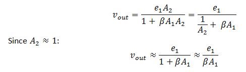
The distortion is attenuated at the output by the feedback fraction times the gain of the first stage. The gain of the output stage does not contribute significantly to the attenuation of the first-stage distortion.
For the distortion at the output stage,
The DC open-loop gain of the amplifier,
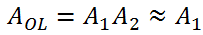 , appears in the amplifier specification.
The distortion at both the input and output stages is attenuated by approximately the loop gain βA1, which is the open-loop gain of the amplifier times the feedback factor.
For the noninverting amplifier circuit, the signal gain is
 , which is also the noise gain.
Hence, the attenuation of the distortion is nearly inversely proportional to the signal gain. In other words, high-gain circuits have more distortion than low-gain circuits.
Signal gain is only one culprit of increasing distortion. The frequency of the input signal increases distortion even more significantly for three reasons. The first is that the open-loop gain of the amplifier decreases with signal frequency, as shown in Figure 3.
 Figure 3 OPA836Open-loop Gain and Phase
vs. Frequency
Figure 3 OPA836Open-loop Gain and Phase
vs. FrequencyPast the dominant pole at 40kHz, the open-loop gain is falling at a rate of 20dB per decade of frequency. Since this roll-off is true for any op amp, the gain-bandwidth product determines the open-loop gain at any frequency between the dominant pole and the gain-bandwidth product. The open-loop gain in this frequency range is directly proportional to the gain-bandwidth product.
The second reason distortion increases with signal frequency is that the open-loop phase lag of the amplifier increases with frequency. Note that the open-loop phase lag is 45 degrees at the frequency of the dominant pole. The fraction of the distortion fed back to the amplifier stage that created the distortion has a phase lag with respect to the distortion itself. This phase lag – which for a single frequency is a time delay – reduces the attenuation of the distortion. Higher-bandwidth amplifiers have higher dominant poles, so they can feed back the distortion to its source with less time delay, which better attenuates the distortion.
The third reason distortion increases with signal frequency is that the distortion appears as multiples of the signal frequency, with the second and third harmonic of the signal the most significant sources of distortion. My statements in the previous paragraph about open-loop gain and phase lag refer to two and three times the signal frequency for the second should and third harmonics, respectively.
Figure 4 shows the effects of frequency on distortion for the OPA836 in a noninverting configuration with a gain of one (a buffer configuration).
 Figure 4 OPA836 Harmonic Distortion vs.
Frequency
Figure 4 OPA836 Harmonic Distortion vs.
FrequencyNote that the OPA836 has a gain-bandwidth product of 110MHz. At 10MHz (one-tenth the gain-bandwidth product), the second and third harmonic distortions are already up to -42 and -45dBc, respectively.
The bottom line is that the bandwidth of the amplifier is critically important to getting acceptable distortion.
Additional Resources
- Check out this white paper on designing for low distortion with high-speed op amps.
- Learn more about TI’s high-speed amplifiers.
- Read this blog post on how to optimize differential amplifier noise.
IMPORTANT NOTICE AND DISCLAIMER
TI PROVIDES TECHNICAL AND RELIABILITY DATA (INCLUDING DATASHEETS), DESIGN RESOURCES (INCLUDING REFERENCE DESIGNS), APPLICATION OR OTHER DESIGN ADVICE, WEB TOOLS, SAFETY INFORMATION, AND OTHER RESOURCES “AS IS” AND WITH ALL FAULTS, AND DISCLAIMS ALL WARRANTIES, EXPRESS AND IMPLIED, INCLUDING WITHOUT LIMITATION ANY IMPLIED WARRANTIES OF MERCHANTABILITY, FITNESS FOR A PARTICULAR PURPOSE OR NON-INFRINGEMENT OF THIRD PARTY INTELLECTUAL PROPERTY RIGHTS.
These resources are intended for skilled developers designing with TI products. You are solely responsible for (1) selecting the appropriate TI products for your application, (2) designing, validating and testing your application, and (3) ensuring your application meets applicable standards, and any other safety, security, or other requirements. These resources are subject to change without notice. TI grants you permission to use these resources only for development of an application that uses the TI products described in the resource. Other reproduction and display of these resources is prohibited. No license is granted to any other TI intellectual property right or to any third party intellectual property right. TI disclaims responsibility for, and you will fully indemnify TI and its representatives against, any claims, damages, costs, losses, and liabilities arising out of your use of these resources.
TI’s products are provided subject to TI’s Terms of Sale (www.ti.com/legal/termsofsale.html) or other applicable terms available either on ti.com or provided in conjunction with such TI products. TI’s provision of these resources does not expand or otherwise alter TI’s applicable warranties or warranty disclaimers for TI products.
Mailing Address: Texas Instruments, Post Office Box 655303, Dallas, Texas 75265
Copyright © 2023, Texas Instruments Incorporated