SSZTBY1 november 2015

Standby power which is generally called vampire power or leaky electricity is one of the major sources of power loss in a system. You may think that your system is off and there is no power consumption but in reality even if the power is turned, a part of the appliance is still running and using up valuable power.
Handling power in standby mode is becoming very difficult with the introduction of standards like ISO 62310, which defines rigorous test procedures to test the power. These stringent test procedures and requirements make it difficult for the appliances to meet the standards.
With todays’ implementation of appliances, the power is handled with the help of a microcontroller, which of course consumes power to operate. While crucial to industrial designs, microcontrollers also make it difficult for the system designed to eliminate leaky power. This problem can easily be solved by designing a system in a way that eliminates the use of unnecessary components DC/DC converters are needed to power the system processor and other blocks of the system, and when standby mode is activated, these DC/DC converters then need to be turned off. By using integrated power management IC (PMIC) solutions, designers can control the power transitions of these DC/DC converters with inbuilt memory that holds the power sequence to control these converters.
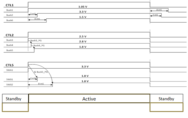
 Figure 1 Control Pins for Power State
Transitions
Figure 1 Control Pins for Power State
TransitionsThe Figure 1 shows the transitions between system standby state and active state using the three pins on the system. These control pins CTL1, CTL2, CLTL5 receive a signal from the processor always on logic and transfers the appliance into standby mode, saving the need for a secondary driver like a microcontoller to drive these pins. All supplies must exceed a user-defined sequence-up threshold within the configured power-good timer time out. If any supply fails to turn on properly, a sequence fault occurs, and all controlled supplies are shut down. When all supplies reach their sequence-up threshold, the supply monitor begins. The controlled supplies sequence-up with user-configured order of rails and inter-rail delays are then saved in the inbuilt one time programmable memory. It eliminates the need for an external microcontroller on the system that issues commands to the point-of-load power supply to transfer the system in lower power mode.
Using a PMIC saves users time and effort configuring software that controls the power sequence when done using a discrete point of load solution. Usually a processor needs to send a software command to power supply to shut down the supply when in standby mode in order to save power. The commands are programmed by the software designer and loaded in the processor. When you use a PMIC you don’t need software designer to write these commands because these commands comes already saved in the PMIC, saving your software designer’s time.
We’ve looked at ways PMICs allow you to eliminate the needs of redundant devices on the system and allows you to keep maximum components off during standby mode by preprogramming the sequence in its memory. Doing this allows you to reach the lowest possible power consumption in standby mode, thus reducing vampire power!
What standby power numbers you are trying to achieve with your system?