SSZTC61 September 2015 TPS53647
There has been much discussion in previous Power House blogs about the benefits of PMBus™ and how a PMBus point-of-load solution can obtain these benefits. But what about really high-current ASIC core rails that require multiphase converters?
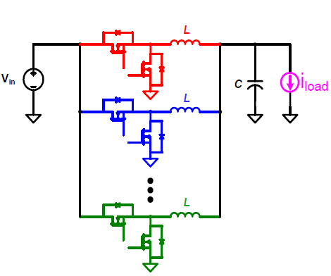
Enterprise servers and switches, storage attach networks, base stations, and FPGA testers are examples of end equipment that use high-current ASICs, DSPs, FPGAs and DDR memory chips. These applications require up to 100A or more of output current. A multiphase converter is the ideal solution for these high currents as it reduces the input root mean square (RMS) current (requires fewer input capacitors) and reduces the output ripple current (requires fewer output capacitors). As well, a multiphase converter enables faster load transient response (requires smaller inductors), while enabling better thermal distribution and higher output power capacity (see Figure 1).
 Figure 1 Multiphase Voltage
Regulator with Buck Stages Staggered Out-of-phase (Multi-phase).
Figure 1 Multiphase Voltage
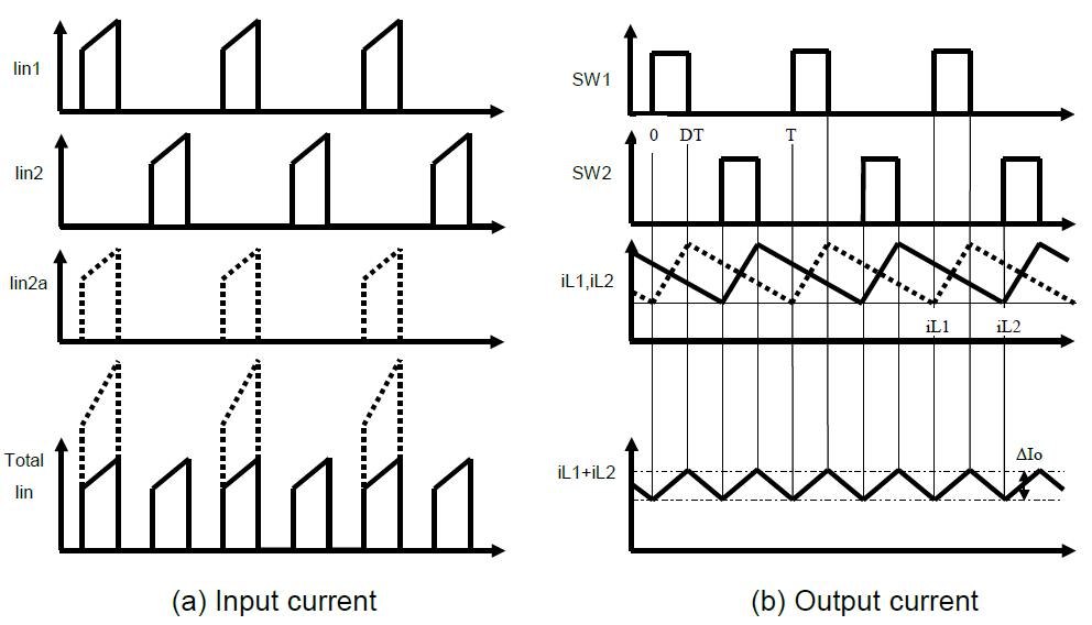
Regulator with Buck Stages Staggered Out-of-phase (Multi-phase).The size and cost of both input and output capacitors are greatly reduced as a result of ripple current interleaving since the input and output ripple currents in each phase cancel each other out (see Figure 2).
 Figure 2 Multiphase Regulator
Input/output Ripple Current Cancellation.
Figure 2 Multiphase Regulator
Input/output Ripple Current Cancellation.One of the major challenges of multiphase converter design is how to maintain and guarantee current sharing (also known as current balance) in each phase, not only in steady state (no major changes in output current demand), but also in dynamic state (during load transients).
The average current imbalance is a result of the current sensing loop and comes from:
- Current sense amplifier offset difference
- Current sense error amplifier gain difference
- Current sensing element tolerance (resistor, inductor DC resistance or MOSFET Rds(on)
- Mismatching contribution ratio for the architecture with current sharing bus
- Thermal/temperature difference for individual phase
The dynamic current imbalance is also a result of various factors:
- Impedance difference and current sharing loop bandwidth limitation
- Current sensing network resistor-capacitor (RC) tolerance - RC for individual phases are different
- Dynamic load
- Phase shedding/adding on the fly
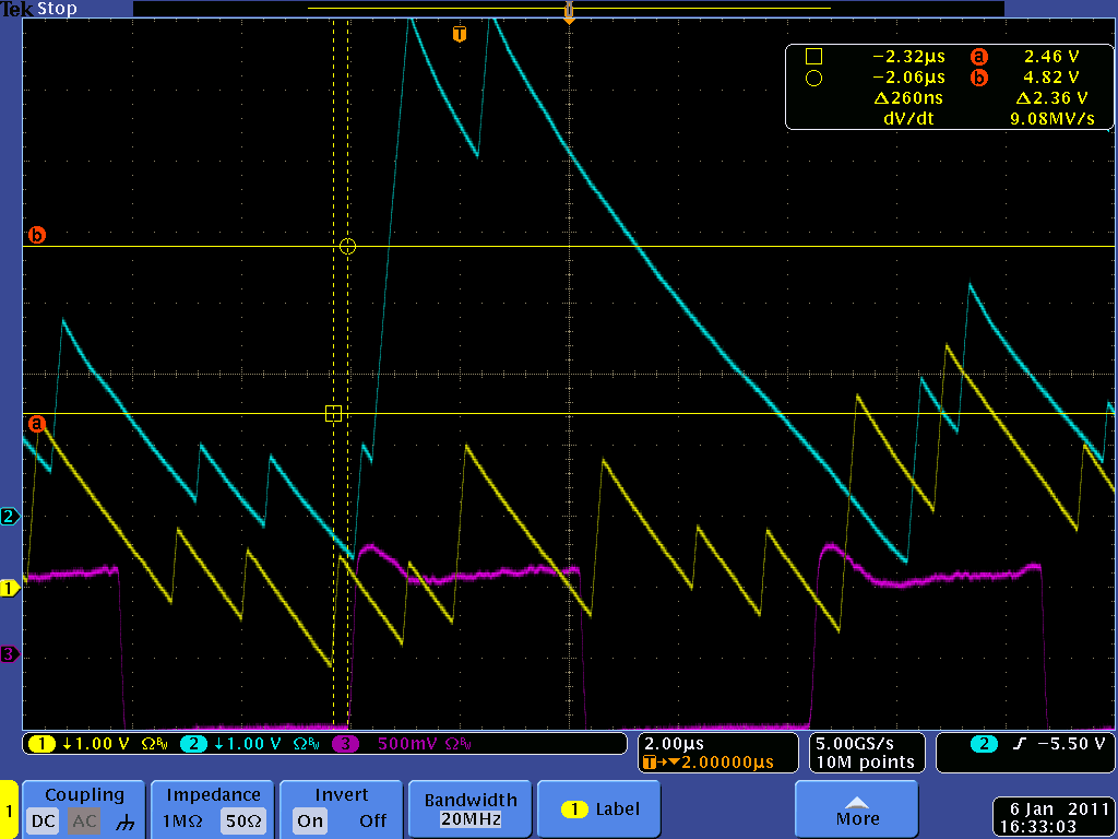
The impact of current imbalance especially during load transients could be very severe and could saturate the inductor, leading to overheating and collapse of the power supply. The lack of tight phase-to-phase current balance forces power supply engineers to overdesign the inductor in each phase to accommodate the extra current being absorbed which, in turn, makes the power supply bulkier and more expensive (see Figure 3).
 Figure 3 Multiphase Regulator Phase
Imbalance During a Load Transient – No Ripple Cancellation.
Figure 3 Multiphase Regulator Phase
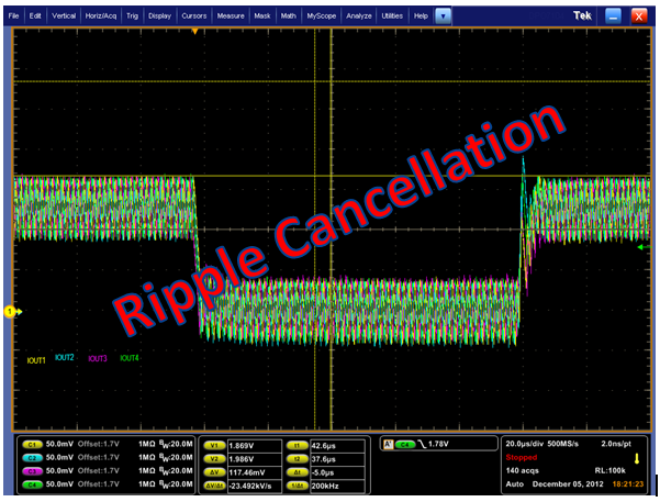
Imbalance During a Load Transient – No Ripple Cancellation.The TPS53647 is a high-current, multi-phase, step-down controller that features TI’s patented AutoBalance phase-to-phase current balance technology that eliminates this headache for engineers. The basic mechanism for current sharing is to sense the average phase current, then adjust the pulse width of each phase to equalize the current in each phase. With AutoBalance technology, the currents are amplified, filtered and compared with the average current. At each on-time, the reference (DAC voltage) is tweaked by a voltage equivalent to a K factor times the phase current minus the average current. The filtering is very light and the overall system response to balance the currents is less than 25us. This filtering enables a very tight phase-to-phase current balance (see Figure 4). As well, since the design engineer knows very accurately the current each phase will carry, he has the flexibility of using a smaller inductor in each phase, resulting in a smaller, more reliable and lower-cost multiphase power supply.
 Figure 4 TPS53647 AutoBalance Phase
Current Sharing.
Figure 4 TPS53647 AutoBalance Phase
Current Sharing.The TPS53647 also operates as a full PMBus 4-phase driverless PWM controller with configurable settings via non-volatile memory or extensive resistor pin-strapping. The PMBus interface provides telemetry of voltage, current, power, temperature and fault conditions.
Additional Resources
-
See TI’s full portfolio of V-Core multiphase regulators and DC/DC multiphase products.
-
Order an evaluation module for the TPS53647.
-
Download the high efficiency, scalable 3-phase 1V/90A point-of-load for ASIC processors reference design.
-
Start a multiphase converter design now in WEBENCH Power Architect.