-
Motor Drive Forum Top FAQs: Understanding Current Ratings
Motor Drive Forum Top FAQs: Understanding Current Ratings
Nicholas Oborny
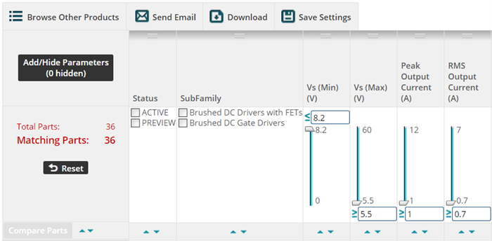
If you have ever looked for a Texas Instruments device, you have likely seen the tool shown in Figure 1. This product selection tool is a mighty instrument that can help you swiftly review hundreds upon hundreds of devices.
 Figure 1 Product Selection Tool
But as the saying goes, garbage in gets you garbage out. So understanding the various specifications of the devices you’re searching is critical to finding the right one for your application. In this installment of our series on Motor Drive forum FAQs, I’ll focus on one of the most misunderstood motor driver specifications: driver current ratings. The two drive-current parameters I’ll examine are peak output current and root mean square (RMS) output current.
The peak output current is the maximum current that the motor driver can deliver, ignoring the thermal limitations of the device and its package. This limit is generally set by the motor driver’s overcurrent protection (OCP) (Figure 2).
 Figure 2 OCP Limit (Peak Output
Current)
Figure 2 OCP Limit (Peak Output
Current)Protection limit example from the DRV8840 datasheet
Attempting to draw more current than the OCP allows will result in a shutdown of the drive stage. One exception to the peak output current limit is that the motor driver will briefly allow a higher current during the OCP’s deglitch timer. The deglitch timer ensures that noise from switching or output capacitors does not trip the OCP and cause a shutdown.
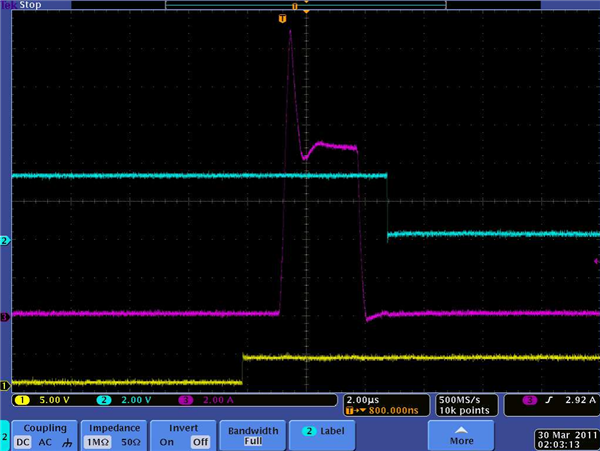
The waveform in Figure 3 shows a typical OCP event during a short-circuit condition on the motor-driver outputs. The yellow trace is the input signal, the blue trace is the fault output signal and the pink trace is the current through the output stage. Initially, the current rises quickly. After a brief overshoot, which is not a problem for the output stage, the current is limited to approximately 9A by an analog current limit. In approximately 2.5µs, the OCP deglitch timer expires and the current stalls at the analog current limit of 9A, exceeding the OCP limit. On this device, the OCP level is approximately 3A. At this point, the output stage is disabled, the current drops to zero and a fault occurs.
 Figure 3 OCP Event
The RMS output current is the maximum RMS (or DC) current that the motor driver can support under a fixed set of conditions. These conditions typically include operating at a nominal voltage, a 25°C ambient temperature and a standard JEDEC-specified printed circuit board (PCB). This limit is generally set by the motor driver’s overtemperature protection. Once the device passes the overtemperature limit, the driver stage will shut down. This ensures that the device is not used outside of its safe operating area.
 Figure 4 Overtemperature Limit from the
DRV8840 datasheet
Figure 4 Overtemperature Limit from the
DRV8840 datasheetAdditional Resources:
- Learn more about thermal considerations at TI.com/thermal.
- Read this "Understanding Motor Driver Current Ratings” application note for details about output current ratings and the protection schemes used by TI motor drivers.
- Search existing Q&As or ask the Motor Application team a question on TI E2E™ Motor Drive community.
- Read other blog posts on the most frequently asked questions from the Motor Drive forum.
IMPORTANT NOTICE AND DISCLAIMER
TI PROVIDES TECHNICAL AND RELIABILITY DATA (INCLUDING DATASHEETS), DESIGN RESOURCES (INCLUDING REFERENCE DESIGNS), APPLICATION OR OTHER DESIGN ADVICE, WEB TOOLS, SAFETY INFORMATION, AND OTHER RESOURCES “AS IS” AND WITH ALL FAULTS, AND DISCLAIMS ALL WARRANTIES, EXPRESS AND IMPLIED, INCLUDING WITHOUT LIMITATION ANY IMPLIED WARRANTIES OF MERCHANTABILITY, FITNESS FOR A PARTICULAR PURPOSE OR NON-INFRINGEMENT OF THIRD PARTY INTELLECTUAL PROPERTY RIGHTS.
These resources are intended for skilled developers designing with TI products. You are solely responsible for (1) selecting the appropriate TI products for your application, (2) designing, validating and testing your application, and (3) ensuring your application meets applicable standards, and any other safety, security, or other requirements. These resources are subject to change without notice. TI grants you permission to use these resources only for development of an application that uses the TI products described in the resource. Other reproduction and display of these resources is prohibited. No license is granted to any other TI intellectual property right or to any third party intellectual property right. TI disclaims responsibility for, and you will fully indemnify TI and its representatives against, any claims, damages, costs, losses, and liabilities arising out of your use of these resources.
TI’s products are provided subject to TI’s Terms of Sale (www.ti.com/legal/termsofsale.html) or other applicable terms available either on ti.com or provided in conjunction with such TI products. TI’s provision of these resources does not expand or otherwise alter TI’s applicable warranties or warranty disclaimers for TI products.
Mailing Address: Texas Instruments, Post Office Box 655303, Dallas, Texas 75265
Copyright © 2023, Texas Instruments Incorporated