SSZTCH0 july 2015
Unlike traditional pulse-width modulation (PWM) power converters, resonant converter output voltages are regulated by frequency modulation. Therefore, the design methodology of a resonant converter will be different from a PWM converter.
Among various types of resonant converters, the LLC series resonant converter (LLC-SRC) in Figure 1 attracts interest because of its better output regulation, lower circulating current and lower circuit cost.
 Figure 1 LLC-SRC with AC Input/output
Voltage
Figure 1 LLC-SRC with AC Input/output
VoltageThe series resonant characteristics allow the switching network in a DC/DC LLC-SRC, such as that shown in Figure 2, to have very wide region of zero-voltage switching (ZVS); hence, the LLC-SRC can easily achieve over 94% efficiency in front-end power-supply applications and operate at a high switching frequency.
 Figure 2 LLC Resonant Half-bridge
Converter
Figure 2 LLC Resonant Half-bridge
ConverterSimilar to the design process for PWM converters, the first step when designing an LLC-SRC is to select the desired operation frequency at full load. The remaining steps are different, because there is no duty-cycle factor in a resonant converter. The duty cycle remains unchanged in an LLC-SRC and is ideally 50%. Figure 3 shows a design flow chart for an LLC-SRC from TI Power Supply Design Seminar topic “Designing an LLC Resonant Half-Bridge Power Converter.”
 Figure 3 LLC Resonant Half-bridge
Converter Design Flow Chart
Figure 3 LLC Resonant Half-bridge
Converter Design Flow ChartNotice that Mg is the DC voltage gain, Ln is the ratio of Lm and Lr, and the quality factor is defined as Equation Figure 1:
") Figure 4 (1)
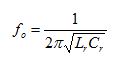
Figure 4 (1)Also, fn is the normalized frequency defined as fn = fsw/fo, where
The gain curves in both the Mg/Qe and Mg/fn charts are derived from the LLC resonant tank shown in Figure 1, which is also a linearized circuit of a LLC resonant half-bridge converter.
Figure 3 provides a simple circuit parameter selection process of an LLC resonant half-bridge converter. By checking the fn_min, fn_max locations on the gain curves, you will be able to design a high-efficiency LLC resonant half-bridge converter with ZVS on the switching network under all input conditions.
When designing a LLC resonant half-bridge converter, keep in mind that:
- fn_min needs to be above the ridges of the gain curves in the Mg/fn chart at all times. This is to make sure that the MOSFETs maintain ZVS.
- LLC-SRC efficiency can only be optimized at one operation point. When fsw = fo, the series Lr and Cr become zero impedance (Figure 5); the converter has best efficiency at that point. You will need to decide the line/load condition that you want to optimize and make sure that your switching frequency is at resonant frequency at that condition.
 Figure 5 LLC-SRC with AC Input/output
Voltage When Fsw = Fo
Figure 5 LLC-SRC with AC Input/output
Voltage When Fsw = FoAdditional Resources
- Find more information about LLC-SRC design and optimization in the TI Power Supply Design Seminars papers.
- Read my previous blogs on LLC converters