SSZTCN3 june 2015
Welcome to the second post in this series on the controller area network (CAN), which is increasingly being used in industrial applications. In this post, I’ll focus on the signaling levels found on a CAN bus, so that designers will understand the origin of CAN’s reputation for noise immunity.
As stated in my first post, CAN is a serial, two-wire, differential bus technology. This means that data is sent one bit at a time through two complementary signals on the controller area network high (CANH) and controller area network low (CANL) bus wires.
To effectively explain the different types of signals, it’s useful to first understand a typical CAN application. Every CAN application consists of a microcontroller with built-in CAN controller and a transceiver that is tied to the bus. A discrete implementation of this is shown in Figure 1. The two types of signals that are processed by the CAN transceiver are single-ended signals (TXD and RXD) and differential signals (CANH and CANL). During normal operation, the CAN transceiver converts the single-ended logic-level output signal (TXD) from the CAN controller to a differential signal. It also converts the differential signal on the bus back to a single-ended logic signal (RXD) for input into the CAN controller. Essentially, the transceiver provides differential drive and differential receive capability to and from the CAN bus.
 Figure 1 CAN Controller and CAN
Transceiver
Figure 1 CAN Controller and CAN
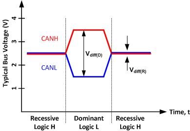
TransceiverThe CAN bus has two logical states: dominant and recessive. The dominant state occurs when a logic low level is applied to the transmit input pin (usually called TXD) of the transceiver. The recessive state corresponds to a logic high level on the transmit input pin of the transceiver. Figure 2 shows these two states.
 Figure 2 CAN Bus Signal Levels
As you can see, in the recessive state both the CANH and CANL bus pins are biased to the same level: approximately 2.5V. During the dominant state, the CANH bus pin is biased to a higher voltage potential (approximately 3.5V) and the CANL bus pin is biased to a lower voltage potential (approximately 1.5V). By subtracting the voltage potential of the two bus pins, you can determine the logical state of the bus using the equation below. When the Vdiff value on the bus is less than 0.5V, the bus is considered to be in a recessive state. Alternately, Vdiff values greater than 0.9V indicate that the bus is in a dominant state. Lastly, for Vdiff values between 0.5V and 0.9V, the bus state is undefined. Since the difference between the two signals is used to define the state of the bus, this signaling type is known as differential signaling. Additionally, the CANH and CANL signals are commonly referred to as complementary singles since you need to know the voltage potential of both signals to determine the logical state of the bus.

The recessive state will only exist on the bus if all transceivers connected to the bus are transmitting a recessive state, because the recessive state is weakly biased, while the dominant state is strongly biased. This is analogous to a wired logical AND connection. All transceivers must be transmitting a logical high signal for the bus output to be logical high. If even one transceiver transmits a logical 0, the entire bus will follow this state and will be in the dominant state.
Now that you know what the differential bus signals on a CAN bus look like, stay tuned for my next post which will describe the typical driver topology that is used to create these bus signals. Feel free to post any questions or comments below.
Additional Resources:
- Read Part 1 of this series: “CAN we start at the very beginning?”
- Check out the new CAN page with information on our products, support resources and technical documents.
- Polarity Correcting Isolated CAN Reference Design