-
Are you ready for the emerging automotive radar satellite architecture?
Are you ready for the emerging automotive radar satellite architecture?
With worldwide New Car Assessment Program safety ratings and regulations growing more stringent toward active safety functions, safety is a nonnegotiable feature in today’s vehicles. Car manufacturers across the globe are meeting these safety requirements and targeting higher levels of autonomous driving by continuously enhancing advanced driver assistance systems (ADAS) features within their vehicles, including automatic emergency braking (AEB), adaptive cruise control (ACC)and advanced lane centering. To support these features and meet safety regulations, the number of radar sensors around the car is increasing.
Evolving vehicle architectures
One way automotive system designers are addressing the implementation of ADAS features is by reconsidering the structure and integration of electrical and electronic systems architectures. The typical architecture today is edge architecture, which consists of highly intelligent radar sensors streaming processed data through a Controller Area Network or 100 Mb Ethernet interface to an ADAS electronic control unit (ECU). These sensors are designed for high performance and consist of a processor and often a specialized accelerator to perform range, Doppler and angle fast Fourier transform (FFT), along with subsequent high-level algorithms for object detection, classification and tracking. The final object data from each edge radar sensor is then sent to the ADAS ECU. Figure 1 illustrates edge architecture.

 Figure 1 Radar sensors in an edge architecture connected to an ADAS ECU
The edge architecture is evolving and giving way to satellite architectures, where the sensor heads strewn around the car stream pre-processed range FFT data to a powerful central ECU through a high-speed 1 Gb Ethernet interface. A significant portion of the data processing is offloaded to the central ECU (Figure 2). Satellite architecture enables centralized data processing using minimally processed data at the central processor unlike edge architecture, where individual radar sensors conduct all data processing independently.

 Figure 2 Radar sensors in a satellite architecture connected to a central ECU
Benefits of satellite architecture
Centralized processing enables the implementation of effective sensor fusion algorithms, resulting in more accurate decision-making. An apt parallel is how the human brain makes decisions based on inputs from both eyes instead of each eye deciding independently. Original equipment manufacturers (OEMs) can deploy algorithms for increasing angular resolution (distributed aperture radar), maximum velocity or even machine learning algorithms for object classification. The fusion of sensor inputs coupled with these algorithms improves sensing performance and results in a comparatively precise perception map. For automakers, this translates to an increased autonomy level. For drivers and passengers, it means safer cars.
In addition, using satellite radar sensors enables system scalability and modularity. The ability to place sensors in more convenient places around the car enables many ADAS applications. It is possible to adjust the degree of coverage just by changing the number or configuration of the sensors, thus scaling a single platform from a cost-sensitive low-end vehicle to a differentiated premium vehicle offering with different levels of autonomy.
Satellite architecture adds value through a sensor fusion algorithm and the larger computing capability in the central ECU. Simplified satellite sensors and differentiation through software can help reduce system complexity and offer new ways of creating value.. Additionally, using satellite radars gives automakers the option to use over-the-air software updates to improve system performance and enhance security. These multiple benefits – performance, scalability and simplicity – all contribute the prominence of the satellite architecture in the automotive industry.
A radar sensor designed for satellite architecture
TI has designed the AWR2544 radar-on-chip sensor specifically for satellite architecture. It features an integrated 77-GHz transceiver with four transmitters and four receivers, providing increased range detection and better performance. It also includes a cost-optimized radar processing accelerator and a throughput-enhanced 1-Gbps Ethernet interface to generate and stream rangeFFT-compressed data. The device is Automotive Safety Integrity Level B-capable and provides a secure execution environment through a hardware security module.
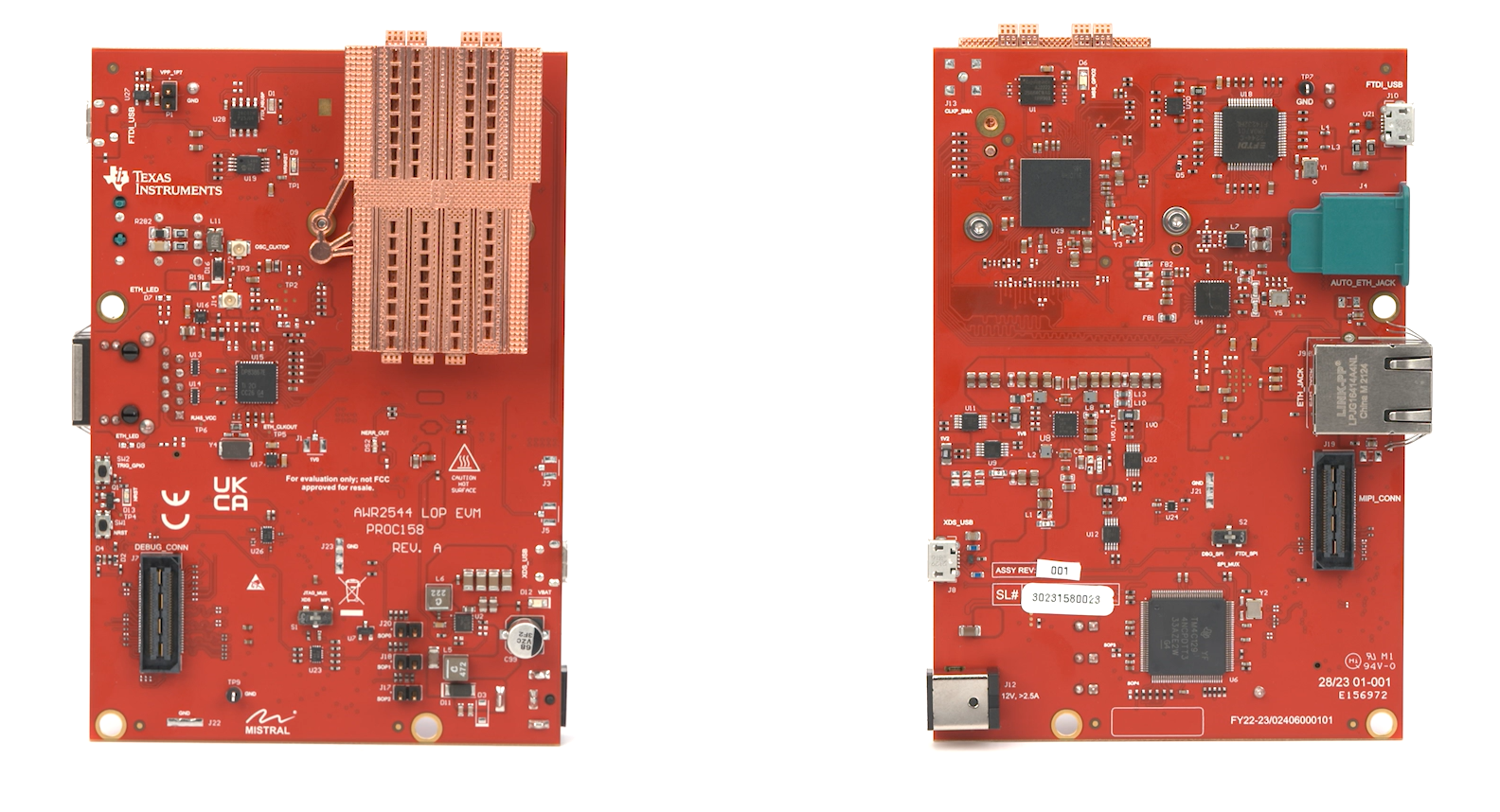
The device is also engineered with TI’s launch-on-package (LOP) technology, which enables direct signal transmission from the package-radiating element to the 3D antenna through a wave guide within the printed circuit board (PCB). Figure 3 shows the AWR2544LOP evaluation module with a 3D waveguide antenna.
 Figure 3 The AWR2544LOP EVM
At the system level, LOP technology improves performance through an increased signal-to-noise ratio, eases thermal management, lowers cost by avoiding costly RF PCB material, and enhances flexibility by enabling PCB reuse across multiple sensor designs.
TI also offers a compatible, safety-enhanced and optimized power-management integrated circuit to ease system implementation. The LP87725-Q1 features three low-noise buck converters, one low-dropout regulator and one load switch for powering AWR2544-based satellite architecture, along with an Ethernet physical layer.
Conclusion
The ADAS applications continue to evolve in order to keep pace with rising autonomy levels and safety requirements. As new architectures like satellite architecture emerge, the sensing and processing technology in these systems must also evolve to support new capabilities. Devices like the AWR2544 radar sensor give automotive system designers flexibility when adopting these trends and help create safer, smarter vehicles for everyone.
Additional resources
- Learn more about TI’s radar sensor portfolio.
- Learn more about our power-management integrated circuit solutions.