SSZTCV0 July 2021 UCC256404
Special considerations must be taken when designing power supplies for audio amplifiers. The nonlinear nature of audio signals poses a different design challenge compared to standard isolated power supplies. This Power Tip covers the must-knows of designing a half-bridge inductor-inductor-converter (LLC) series resonant converter (HB LLC-SRC) for audio applications.
Audio power
One thing you find in the broad field of electrical engineering is that different industries, or even companies, may use different language to describe the same subject. For a successful design, it is essential for power and audio engineers to understand each other.
Two terms that need be defined first are peak power and continuous power. Peak power is the maximum instantaneous audio power. It will determine how much power to design for the supply to physically output. Continuous power is the audio power averaged over a period of time. In the context of power supply design, continuous power is the specified output power the system can supply without exceeding component temperature or average current ratings. Figure 1 provides an example of the peak and continuous audio levels. They are related by the crest factor, a measure of the ratio of peak to root-mean-square (RMS) value of a waveform.
 Figure 1 This graph shows continuous
and peak power audio levels.
Figure 1 This graph shows continuous
and peak power audio levels.It can also be represented in decibels by Equation 1:
RMS is a misnomer in audio power, as the value is not technically the calculated RMS value of the power waveform. Another article could be written on the complexities of how audio amplifiers are specified. Understand that industry standards for rating amplifier power level do not necessarily make clear what the power supply requirements are in terms of peak and continuous power.
As an example, consider an LLC series resonant converter (LLC-SRC) design for a 400-W audio amplifier. Without prior knowledge of audio systems, you may design an excellent 400-W power supply. But when it is time to power up the amp, the supply fails, or audio quality is poor. The LLC converter gain curve will typically be designed based on the maximum load and operate near the series resonant frequency at the minimum line condition. This approach will normally yield a perfectly good 400-W LLC-SRC, but inside an actual audio system peak powers will actually be greater than the 400-W rating of the amp. At a minimum, the continuous and peak power should be specified before starting your power supply design.
For the 400-W amp example, appropriate power levels for a consumer product playing compressed music could be a continuous power of 200 W and a peak power of 800 W for 15 ms. This represents a crest factor of 12 dB, which is typical for processed music. Unprocessed audio will be around 18-20 dB and movie audio can be >20 dB. Ultimately, the ratio of peak to continuous power depends on the specific application, so it is important to clearly define these early in the design process. Time duration requirements for the different load levels are also useful for optimizing the design. Remember that efficiency of the audio amp will need to be considered, as there will be losses in the amp resulting in a higher load on the power supply.
LLC-SRC design
Once the specifications are finalized, you can proceed with the power supply design. Depending on power quality standards of the region and application, you will likely need a power factor correction (PFC) supply for designs of this power level. The PFC front-end will provide a regulated 400VDC bus that serves as the input to the LLC-SRC.
Like most resonant converters, the first step in designing the LLC-SRC is to select the resonant tank components. This will set the resonant frequency and shape the gain curve. At this step, ensure that the output voltage can be reached at the peak power level. If the resonant tank cannot achieve the required gain, then the output voltage will drop at peak audio, reducing audio quality or shutting down the amp. The peak power duration requirement will typically be too long for the output capacitors to hold up the output voltage, so the power supply needs to be capable of actually providing the entire peak load.
Build in some extra headroom on the peak gain. Physical limitations of transformer construction do not always hit the exact number of turns or inductance. For an audio design where it is necessary to reach high peak powers, it is advantageous to use a discrete resonant inductor to ensure a more precise resonant and magnetizing inductance.
At the peak power, it is important to select components rated to handle the peak currents. When designing the magnetics, make sure that they will not saturate. At the continuous power, it is important to select components and packages based on continuous thermal performance. Designers can undersize some of the packages and use the PCB for thermal management rather than a heatsink.
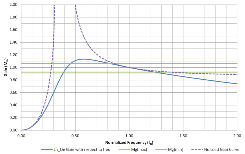
Like any LLC-SRC, shaping the gain curve is an iterative process. Trying to hit certain operating frequencies, resonant currents and voltages and balancing the design between a peak and continuous power level is a challenge. As you go through the calculations, you will need to adjust the magnetizing inductance, resonant inductance, turns ratio and resonant capacitance. 100 kHz is a common resonant frequency target for silicon-based designs. For audio applications it makes sense to target 100 kHz for the continuous power operating point. Figure 2 shows a gain curve shaped for the above example. The operating frequency range is 83–139 kHz.
 Figure 2 This gain curve is shaped for
the LLC-SRC design.
Figure 2 This gain curve is shaped for
the LLC-SRC design.Burst mode
An important aspect of modern LLC-SRC design is burst mode operation for light load efficiency. Burst mode is also used to meet industry standby power regulations. Audible noise is a concern when the burst packet frequency is in the audible noise range, but some LLC resonant controllers like the UCC256404 use a burst mode control law that prevents audible noise generated by the burst frequency. These are three approaches, and possible reasons for choosing them:
- Enable burst mode: Use burst mode to lower standby power consumption without shutting down the main output. Power will be provided to the amp instantaneously, resulting in no delay due to supply startup.
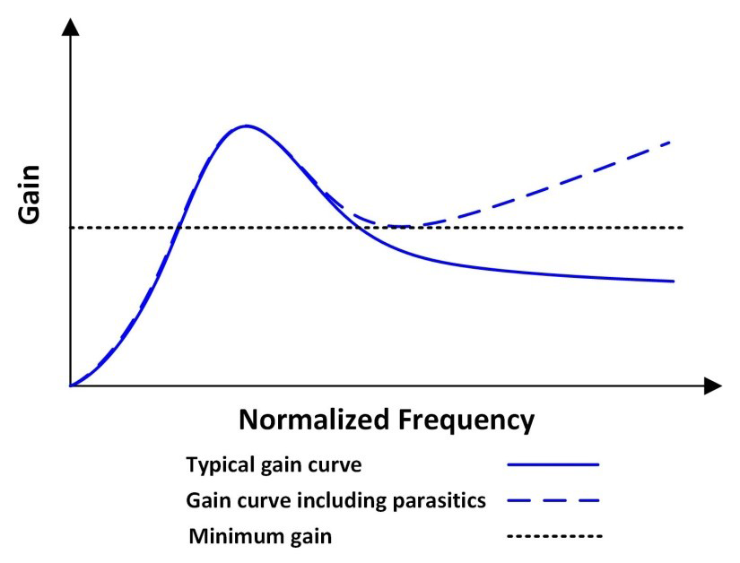
- Disable burst mode: In standby, the converter will need to regulate the output with standard switching operation. This decreases light load efficiency, but can reduce complexity and further eliminates any audible noise concerns, such as the effect of the secondary side rectifier parasitics on the gain curve. Figure 2 shows how the gain curve will actually start to rise at higher frequencies. The supply will lose regulation if the minimum gain cannot be reached.
- External controller disable: Use an external disable circuit to turn off the controller when the audio amp is not running. This lowers standby power further than burst mode but adds cost, as the system now requires an auxiliary power supply. There will also be a startup delay when the amp is ready to output audio.
 Figure 3 The gain curve will start to rise at higher frequencies with burst mode disabled.
The LLC-SRC is a high-performance topology for continuous power ranges between 100 and 500 W. It is an excellent topology for AC-DC systems that require high efficiency and minimum electromagnetic interference (EMI). Resonant converter design is challenging enough, even before being applied to the intricacies of audio systems. The first step is a mutual understanding between the power and audio engineer on the required peak and continuous power levels of the amplifier. Consider the strategies presented above as a starting point of a successful LLC-SRC design for audio applications.
Sources:
- Power Solutions for Class-D Audio Amplifiers, Texas Instruments
- How to Choose a Class-D Audio Amplifier, Texas Instruments
- Pro Audio Reference, Audio Engineering Society