SSZTCV8 February 2024 LM5143A-Q1
Most electronics that go inside the car cabin need to be able to operate at up to 85°C without forced-air cooling. Product qualification requires showing that no component or trace on the board is getting too hot, even at maximum ambient temperatures. Existing methods of testing at elevated temperatures use thermocouples, which can be time-consuming and miss potential hot spots. Thermal cameras will pick up these missed spots and have become the best practice for room temperature tests. Room temperature testing will miss heating effects that only become noticeable in higher-temperature environments.
However, inserting a thermal camera into the 85°C chamber is not advisable as most such cameras cannot withstand above 70°C without damage. Pointing the thermal camera through the glass front of the thermal chamber also will not work, as the glass pane(s) distort the thermal image from the target device.
My proposed solution is to test the electronics in a convection thermal chamber with its door open, but covering the front with cardboard and tape, leaving only a small opening for the front of the thermal camera to get a good, clean thermal image. A thermocouple would be placed inside the chamber very close to the board under test to verify that the 85°C ambient has been achieved. The small opening for the thermal camera should not prevent this, and would allow the camera to be outside the chamber for the actual image.
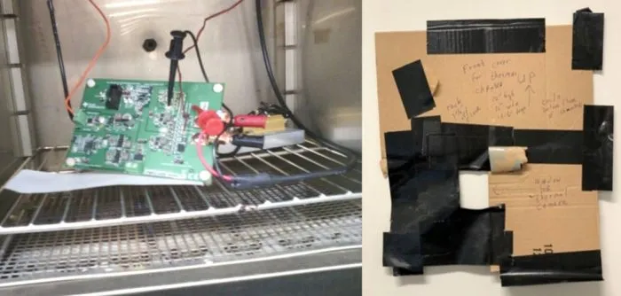
I was able to find an old thermal chamber that only had heating coils below and no fan, relying only on convective airflow for heat transport (Figure 1). Furthermore, this oven did not have an interlock that shut off the coils when the front door was open. Using a newer oven, disconnecting the fan, and defeating the interlocks is another possibility, but not advised, as the manufacturers’ warranty will be voided.
 Figure 1 The setup includes the thermal
chamber and the baffle
Figure 1 The setup includes the thermal
chamber and the baffleTo the left of the board under test are the input 14-V power wires from an external lab power supply standing in for the car battery. To the right of board are load connections to resistors inside the chamber to load the 920 mV output with 22 A to represent the application load. Three monitoring wires can be seen for the thermocouple and output voltage sense (positive and negative); they went to multimeters to monitor temperature (Tektronix TX3) and output voltage (Fluke 87 III).
The Blue M DV-12A (“Gravity Oven”) thermal chamber was used with a front opening of 12 by 12 inches (and 12.5 inches deep), which was covered with the baffle (from Figure 1) during test. Similar ovens are generally available, offered in the several hundred dollar range. The square hole in the baffle was located to allow an external thermal camera (Flir E75) to focus on the hottest area on the board under test.
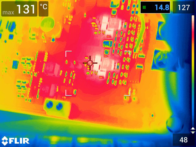
The board was powered with 14-V drawing, almost 2 A during the test, and the baffle cover was placed over the chamber opening. The thermal chamber coils were turned on and the setting adjusted to target 85-87°C on the thermocouple. The overall run took about 30 minutes with three thermal images taken, spaced five minutes apart, to verify that indeed thermal stabilization had been reached. Input current from the lab supply was also monitored to verify this stabilization. Current draw increased about 1% during run as expected due to increased conduction losses in the converters with increased temperature. Figure 2 shows the final thermal image.
 Figure 2 The final thermal image shows
a max temperature of 131°C at the end of the run. Note the green thermocouple
image to the right of the FETs
Figure 2 The final thermal image shows
a max temperature of 131°C at the end of the run. Note the green thermocouple
image to the right of the FETsOutput voltage monitored throughout the run stayed at 919 mV. Thermocouple readings varied between 85 and 88°C as the thermal chamber coils clicked on and off during the last 15-20 minutes of the run. Repeated thermal images over a nine-minute span with the same max temperature verified that thermal stabilization was achieved.
To verify ambient temperature monitoring, a run was done with two thermocouples monitoring the ambient; one as shown in Figure 2 and one slightly below the board. Both monitors read within 1°C of each other. As an additional verification, the run was repeated with a thermocouple glued on the hottest FET, and its max temperature was 4-5°C cooler than what the thermal camera picked up. This also demonstrates that the thermal camera will pick up hot spots missed by the thermocouples.
Overall, this demonstrated a more thorough method of high ambient thermal verification for automotive applications at moderate incremental cost (assuming existing availability of a thermal camera). This method will pick up thermal runaway situations that earlier methods have missed. If a used convection oven needs to be purchased, the savings from not having to glue multiple thermocouples will quickly cover the cost.
Related articles
- Thermocouples: Basic principles and design essentials
- The thermal camera arriveth
- What’s for dinner? Cooking with a temperature sensor
- Book review: A guide to sensors in automotive
- Thermocouples: Simple but misunderstood
- Minimize measurement errors in RTD circuits
- Clever techniques improve thermocouple measurements
Previously published on EDN.com.