SSZTCW2 August 2022
Because servers are essential for handling data communications, the server industry has grown exponentially in parallel with the internet. Although server units were originally based on a PC architecture, a server system must be able to handle the increasing number and complexity of network hosts.
Figure 1 shows a typical rack server system in a data center and a block diagram of a server system. Power-supply units (PSUs) are at the heart of a server system and require a complex system architecture. This article will examine five server PSU design trends: power budget, redundancy, efficiency, operating temperature, and communication and control.
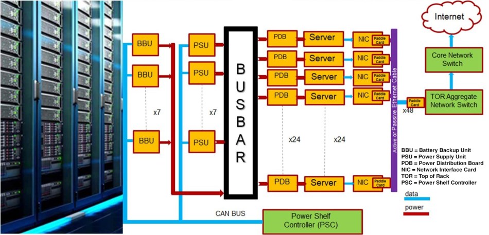 Figure 1 A server system block diagram
along with how a server is positioned in a data center. Source: Texas
Instruments
Figure 1 A server system block diagram
along with how a server is positioned in a data center. Source: Texas
InstrumentsTrend No. 1: Power budget
In the early 21st century, the power budget of a rack or blade server PSU was in the 200-W to 300-W range. At that time, power consumption per central processing unit (CPU) was in the 30-W to 50-W range. Figure 2 shows CPU power consumption trends.
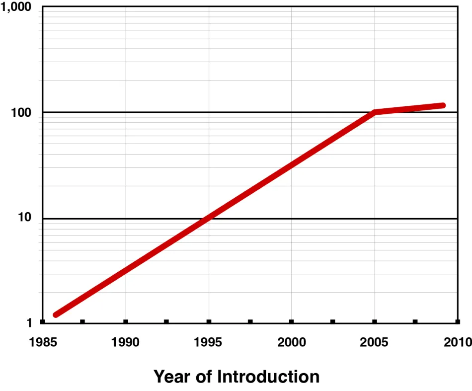 Figure 2 The CPU power consumption
trends for the early 21st century.
Figure 2 The CPU power consumption
trends for the early 21st century.Today, a server CPU’s power consumption is around 200 W—with thermal design power closed to 300 W - greatly increasing the server PSU’s power budget to a range of 800 W to 2,000 W. In order to support more and more server computation requirements such as cloud computing and artificial intelligence (AI) calculations on the internet, servers can include graphics processing units (GPUs) to work alongside CPUs. This inclusion could increase a server’s power demand beyond 3,000 W within five years. However, since most rack or blade server PSUs are still using an AC inlet with up to a 16-A current rating, they will have limited power budgets: around 3,600 W at a 240 VAC input, accounting for converter efficiency. So 3,600 W will still be a server rack PSU’s power limit in the near term.
For the data center power shelf, server PSU designers widely apply the International Electrotechnical Commission (IEC) 60320 C20 AC inlet with 20-A current rating. PSU power budgets are limited by their AC inlet current rating, which allows about 3,000 W in today’s data center PSUs; but in the near future, a data center PSU’s power level could increase to over 5,000 W. To allow a higher power budget per PSU and achieve higher power density, you can also use a busbar for the AC inlet to increase the input current rating.
Trend No. 2: Redundancy
The importance of reliability and availability in a server system necessitates redundant PSUs. If one or more PSUs fail, other PSUs in the system can take over to deliver energy.
A simple server system can have 1+1 redundancy, meaning that there is one active PSU and one redundant PSU in the system. A complex server system might have an N+1 or N+N (N>2) redundancy, depending on system reliability and cost considerations. In order to keep the system operating normally when a PSU needs to be replaced, the system needs a hot-swap (ORing control) technique. And because multiple PSUs deliver power simultaneously in an N+1 or N+N system, server PSUs also require a current-sharing technique.
Even a PSU in standby mode - not delivering power to the output from its main power rail - still requires instant delivery of full power after a hot-swap event, thus requiring constant activation of the power stage. In order to reduce the power consumption of the redundant power supply in standby mode, “cold redundancy” functionality is becoming a trend. The purpose of cold redundancy is to shut down the main power operation or operate in burst mode, enabling the redundant PSU to minimize standby power consumption.
Trend No. 3: Efficiency
Efficiency specifications in the early 2000s were just above 65%; at the time, server PSU designers did not prioritize efficiency. Traditional converter topologies could easily satisfy the 65% efficiency target. But because a server needs to operate continuously, higher efficiency can greatly reduce total cost of ownership.
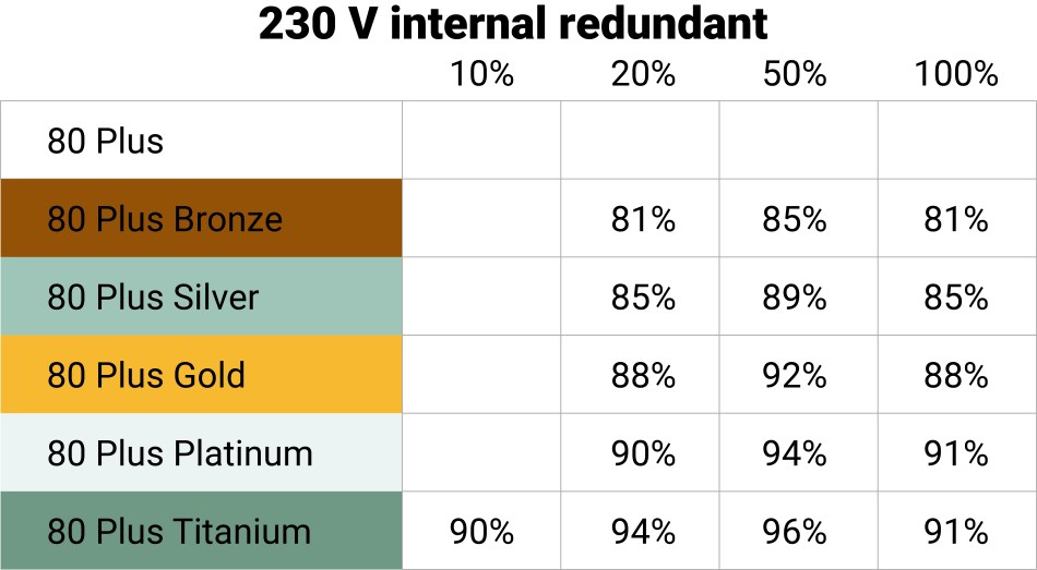
Since 2004, the 80 Plus standard has provided certifications for PC and server PSU systems that can achieve over 80% efficiency. Server PSUs in mass production today mostly achieve the 80 Plus Gold (>92% efficiency) requirement, and some can even achieve 80 Plus Platinum (>94% efficiency).
Server PSUs under development today mainly target the even higher 80 Plus Titanium specifications, which require over 96% peak efficiency at half loads. Table 1 shows the various 80 Plus specifications.
|
Also, according to the Open Compute Project (OCP) open-rack specification that data center PSUs are following, a PSU needs to achieve over 97.5% peak efficiency. Therefore, new topologies such as bridgeless power factor correction (PFC) and soft-switching converters, along with wide bandgap technologies such as silicon carbide (SiC) and gallium nitride (GaN), can help PSUs achieve 80 Plus Titanium and open-compute efficiency goals.
Trend No. 4: Operating temperature
In the context of server PSU thermal management, designers define the ambient temperature at the PSU AC inlet where the fan is located as the server PSU operating temperature. The operating temperature started at 45°C maximum in the early 2000s and today reaches 55°C maximum, depending on the cooling system in the server room.
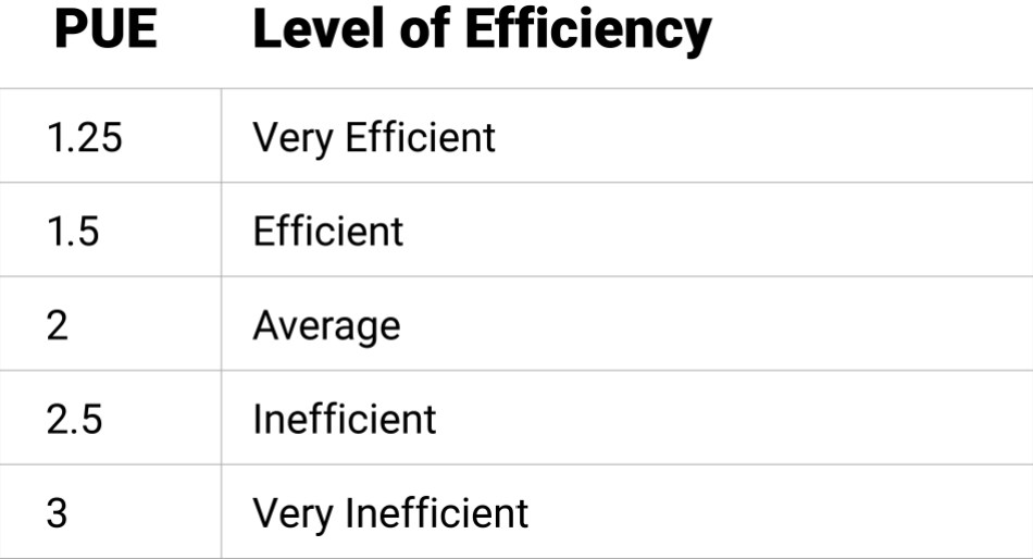
A higher operating temperature reduces the energy costs of a server cooling system. Compared to the capital expenditures of a data center (such as hardware equipment), energy costs as an operating expense are expected to be higher than capital expenditures over time. According to the power usage effectiveness (PUE) standard:
PUE = Total Datacenter Power/Actual IT Power
As shown in Table 2, a lower PUE number means an efficient data center. Figure 3 is an estimation of the PUE number under different operating temperatures. For example, a data center with a PUE of 1.25 can only allow 10% of overall power consumption on its cooling system. This implies the need for a higher operating temperature in a server PSU.
|
 Figure 3 An estimation of the PUE
number under different operating temperatures shows reduced cooling costs with a
higher operating temperature.
Figure 3 An estimation of the PUE
number under different operating temperatures shows reduced cooling costs with a
higher operating temperature.Trend No. 5 Communication and control
Communication and control have played an important role in server power over the years. In the early 2000s, the PSU’s internal information was transmitted to the system side through the System Management Bus interface. In 2007, the Power Management Bus (PMBus) interface added functions, including configuration, control, monitoring and fault management, input/output current and power, board temperatures, fan speed control, real-time update code, overvoltage (current, temperature), and protection. Then, in response to increased demand for data center power shelves, the Controller Area Network (CAN) bus became a part of server power communication.
Power-management controllers have also evolved along with the communication bus. In the early 2000s, analog controllers mainly controlled server PSUs. As more and more control demands increased the need for communication, it became easier to realize those demands with digital controllers. Using digital control also reduces a hardware engineer’s debugging efforts, potentially reducing labor costs during the PSU design and verification stages.
Future development trends for server PSUs
As server power budgets grow while the volume remains fixed, power density requirements will become stricter. Power density has increased from single digits at the beginning of the 2000s to nearly 100 W/in3 on newly developed server PSUs. Improving converter efficiency through topology and component technology evolutions is the solution to achieving high power density.
As was the case with the current, power and efficiency trends, the ideal diode/ORing controller needs to deliver high current in a small package. The ideal diode/ORing controller must also integrate features such as monitoring, fault handling and transient handling to reduce the overall component count and PCB area needed to achieve these functionalities.
For example, a PFC circuit in a server PSU has evolved from passive PFC to active-bridge PFC to active bridgeless PFC. Isolated DC/DC converters have evolved from hard-switching flyback and forward converters to soft-switching inductor-inductor-capacitor resonant and phase-shifted full-bridge converters. Nonisolated DC/DC converters have evolved from linear regulator and magnetic amplifiers to buck converters with synchronous rectifiers. Subsequent increases in overall efficiency reduce internal power consumption and the effort required to resolve thermal issues.
Component technologies applied to server PSUs have also evolved, from IGBTs and silicon MOSFETs to wide bandgap devices such as silicon-carbide MOSFETs and gallium-nitride FETs. The nonideal switching characteristics of IGBTs and silicon MOSFETs limit the switching frequencies below 200 kHz. While wide bandgap devices have switching characteristics closer to ideal switches, using wide bandgap devices can enable higher switching frequencies to help shrink the number of magnetic components used in the PSU.
As the operating temperature increases, components in a server PSU need to handle higher thermal stress, which also drives circuit evolution. For instance, a conventional implementation applies a mechanical relay in parallel with a resistor to suppress the input in-rush current during startup. But because of their bulky size, reliability concerns and lower temperature rating, solid-state relays are now replacing mechanical relays in server PSUs.
The 3.6-kW single-phase totem-pole bridgeless PFC design with >180-W/in3 power density and 3-kW phase-shifted full bridge with active clamp design with >270-W/in3 power density aim to meet common redundant power-supply specifications in servers (Figure 4).
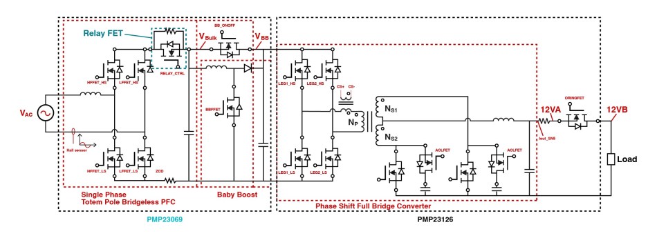 Figure 4 The block diagram shows the
3.6-kW and 3-kW reference designs. Source: Texas Instruments
Figure 4 The block diagram shows the
3.6-kW and 3-kW reference designs. Source: Texas InstrumentsIn the 3.6-kW PFC design, a solid-state relay accommodates a high operating temperature. Here, the LMG3522R030 GaN FET enables the use of a bridgeless totem-pole PFC topology. A “baby boost” reduces the bulk capacitor volume for higher power density.
In the 3-kW phase-shifted full-bridge design, the LMG3522R030 GaN FET helps lower the circulating current and makes it possible to achieve soft switching. An active clamping circuit acting as a lossless snubber enables higher converter efficiency with lower synchronous rectifier voltage stresses. All the aforementioned control requirements are achieved through C2000™ microcontroller acting as digital control processor.