SWAU130A March 2023 – December 2023
3.1.2 Processor and Linux
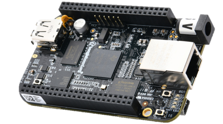
The BP-CC3301 can integrate with a host platform running Linux OS, like the BeagleBone Black (BBB). The BeagleBone Black is a low-cost, community-supported development platform as shown below.
 Figure 3-2 BeagleBone Black Board
To interface with the BP-CC3301 with the BeagleBone Black, the user also needs the BP-CC33xx to BBB Adapter Board.
 Figure 3-3 Adapter Board for the
BeagleBone Black
 Figure 3-4 BP-CC3301 + BBB with Adapter
Board
Figure 3-4 BP-CC3301 + BBB with Adapter
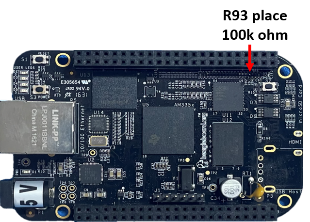
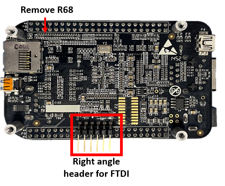
BoardTo make sure the BeagleBone Black boots up from the SD card, TI recommends to add a 100k Ohm resistor for R93 on the top of the BBB, and remove the R68 resistor seen on the bottom of the BBB. Alternatively, you can press and hold the S2 button on the BeagleBone board during power up if the hardware modifications were not made. (see Figure 3-6 and Figure 3-7).
Lastly, adding a right angle header on the bottom of the BBB to easily connect the FTDI cable is optional. When the adapter board is attached to the BBB, the FTDI cable can get pinched between the BBB and adapter board, which can cause communication problems. (see Figure 3-7).
 Figure 3-5 Top View of Modified BBB
 Figure 3-6 Bottom View of Modified BBB