SWCU192 November 2021 CC1312R7 , CC1352P7 , CC2652P7 , CC2652R7
The timer measures signal period and pulse width of two different signals A and B. In this example, it is assumed that both signals have periods less than the counter range. Hence, time-out detection as described in the register documentation is not required. Configure as follows:
- Channel 0:
- AUX_TIMER2:CH0EVCFG. CCACT = PER_PULSE_WIDTH_MEAS
- AUX_TIMER2:CH0EVCFG. EV0_GEN = 1
- AUX_TIMER2:CH0CCFG.CAPT_SRC = Signal A
- AUX_TIMER2:CH0CCFG.EDGE = RISING
- Channel 1:
- AUX_TIMER2:CH1EVCFG. CCACT = PER_PULSE_WIDTH_MEAS
- AUX_TIMER2:CH1EVCFG. EV1_GEN = 1
- AUX_TIMER2:CH1CCFG.CAPT_SRC = Signal B
- AUX_TIMER2:CH1CCFG.EDGE = FALLING
- Timer:
- CTL.MODE = UP_PER
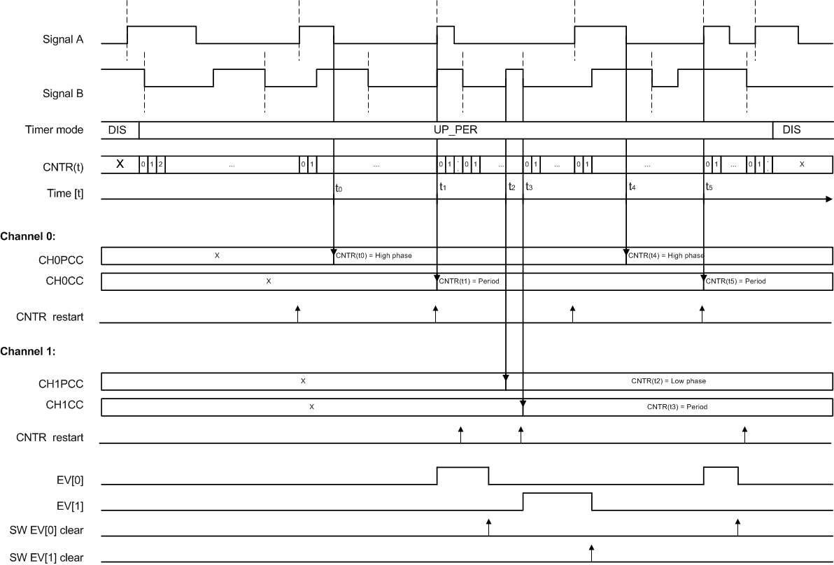
Figure 20-25 shows how the timer counter first synchronizes to signal A. Channel 0 then captures the high phase of signal A into CH0PCC at time t0. Finally, the period of signal A is captured in CH0CC at time t1. At the same time, Channel 0 sets the event output 0 high, and the timer counter starts to synchronize to signal B. Channel 1 then captures the low phase of signal B into CH1PCC at time t2. Finally, the period of signal B is captured in CH1CC at time t3. At the same time, channel 1 sets the event output 1 high, and the timer counter starts to synchronize to signal A. The sequence then repeats itself until it is stopped by the user.
 Figure 20-25 Period Pulse Width
Measurement