SWRA656C May 2020 – October 2022 AWR6843 , AWR6843AOP , IWR1642 , IWR1843 , IWR6443 , IWR6843 , IWR6843AOP
- Migrating to xWR68xx and xWR18xx Millimeter Wave Sensors
- Trademarks
- 1Introduction
- 2xWR1843 Hardware/Software Migration
- 3xWR6843AoP ES2.0 Migration
- 4Helpful Resources
-
5Code Snapshots
- 5.1 SDK 3.3 API Change for MMWave_open
- 5.2 SDK 3.3 API Change for ADCBuf_open
- 5.3 SDK 3.3 API Change for CANFD_init
- 5.4 SDK 3.3 68xx Secondary Bootloader Update
- 5.5 SDK 3.3 16xx vs 68xx: Calibration Frequency Update
- 5.6 SDK 3.3 16xx vs 68xx: SoC Definition Updates
- 5.7 SDK 3.3 16xx vs 18xx: SoC Definition Updates
- 5.8 SDK 3.4 xWR68xx Calibration Frequency Update
- 5.9 SDK 3.4 Object Detect HWA DPC Range FFT Scaling
- 5.10 SDK 3.4 Object Detect Range HWA DPC Radar Cube Format
- 5.11 xWR6843AoP ES1.0 Antenna Geometry
- 5.12 xWR6843AoP ES2.0 Antenna Geometry
- 5.13 xWR6843AoP ES2.0 Antenna Geometry Code Update
- 5.14 Antenna Geometry Structure Usage in mmw demo
- 5.15 xWR6843AoP ES2.0 RX Channel Phase Compensation
- 6References
- 7Revision History
2.1.1 Device Comparison
Table 2-1 lists the key features of the xWR1642 and the xWR1843 devices that need to be considered from Hardware and software migration perspective. For more information, see the device-specific data sheets and the Industrial mmWave Radar Family Technical Reference Manual in Section 6.
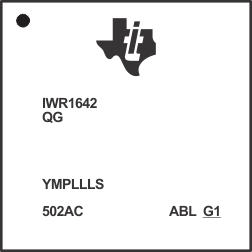
Figure 2-1 and Figure 2-2 show the device symbolization change from xWR1642 to xWR1843 on device part marking.
The left side device marking shows the xWR1642 silicon and the right side device marking shows the xWR1843 silicon. For more details on the device marking, see the device-specific Errata.
 Figure 2-1 xWR1642 Device Marking
 Figure 2-2 xWR1843 Device Marking
| No | Device Feature Differences | xWR1642 | xWR1843 | Hardware and Software Impact |
|---|---|---|---|---|
| 1 | Number of Transmit Channels | 2 | 3 (1) | 3rd Transmitter Antenna need to be designed. Update TX bitmap in chirpCfg |
| 2 | Maximum Sampling Rate | 6.25 MHz complex | 12.5 MHz complex | Higher IF bandwidth and Sampling rates are available on xWR1843 |
| 3 | Max I/F (Intermediate Frequency) | 5 MHz | 10 MHz | |
| 4 | On-chip memory | 1.5MB | 2.0MB | Software can leverage the additional memory if needed. |
| 5 | Radar Accelerator | Not Applicable | Hardware accelerator for FFT, filtering, and CFAR processing | xWR1843 has flexibility of data processing on Hardware accelerator or DSP |
| 6 | Tx beam forming | No support | Supported | xWR1843 has phase shifters which supports the steerable beams. Note: Antennas need to be designed to support TX beam forming operation |
| 7 | MMWAVE-SDK support | SDK 2.1 (LTS) and above | SDK 3.3.0 and above | General software porting required compiling for xWR1843. For more information, see the Section 2.1.4. |