SWRA680 November   2020 CC3100 , CC3120 , CC3135 , CC3200 , CC3220R , CC3220S , CC3220SF , CC3235S , CC3235SF


  1.   Abstract
  2.   Trademarks
  3. 1Crystal Oscillator Basics
    1. 1.1 Crystal Oscillator Model
  4. 2Crystal Selection
    1. 2.1 Crystal Mode of Operation
    2. 2.2 Temperature Tolerance
    3. 2.3 Aging (Long-Term Stability)
    4. 2.4 Crystal ESR
    5. 2.5 Frequency Accuracy
    6. 2.6 Drive Level
    7. 2.7 Selecting a crystal
      1. 2.7.1 Crystal Specifications
      2. 2.7.2 Recommended Crystals for the CC31xx and CC32xx
  5. 3Crystal Tuning
    1. 3.1 The importance of Crystal Tuning
    2. 3.2 Load Capacitance
    3. 3.3 Crystal Tuning With CL
  6. 4Measuring the ppm Error for the Fast Clock (High Frequency)
    1. 4.1 Setting Up for the CC3x00 Devices
    2. 4.2 Setting Up for the CC3x20 and CC3x35 Devices
    3. 4.3 Measuring ppm Frequency Error
  7. 5PCB Layout Guidelines
    1. 5.1 The 32.768-kHz Crystal (Slow Clock)
    2. 5.2 The 40-MHz Crystal (Fast Clock)
  8. 6References

Crystal Oscillator Model

A crystal-based oscillator is formed by placing a crystal in the feedback loop of an oscillator circuit that provides sufficient gain and phase shift around the loop to start and sustain stable oscillations. A simplified electric model of a crystal is shown in Figure 1-1.
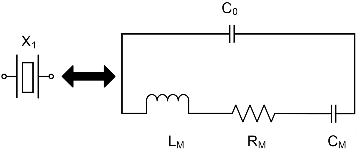
GUID-20200807-CA0I-CR5X-ST6T-NWVBRPZW15VG-low.png Figure 1-1 Crystal Symbol and the Electrical Model

It has R-L-C series components, called motional resistance (Rm), motional inductance (Lm), and motional capacitance (Cm). The capacitor in parallel, C0, is called the shunt capacitance, and models the package capacitance.