SWRA729 April 2022 CC1352P , CC1354P10 , CC2652P
1.1.1 Murata PA IPC Equivalent Circuit
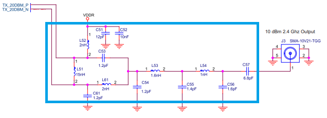
The equivalent circuit of the IPC from Murata is shown in Figure 1-2. The complete specification of their IPC is available from Murata [3]. Murata’s matched balun filter solution implementation contains a DC blocking capacitor (C57) and a bypass capacitor (C51).
 Figure 1-2 Murata CC1352P IPC Equivalent Circuit for 10 dBm PA 2.4 GHz
 Figure 1-3 CC2652P PA IPC EM Rev 1.0 Schematic
The 10 dBm PA IPC was evaluated on the CC2652P PA IPC EM board shown in Figure 1-1 and the schematic is shown in Figure 1-3. The CC2652P PA IPC EM board utilizes two IPCs, one IPC for the Rx / 5 dBm Tx port [6] and the second IPC [3] for the 10 dBm PA section. Only the 10 dBm PA IPC connected to pins 5 and 6 will be discussed in this application note.
CC2652P PA IPC EM board has a common RF port. The Rx / 5 dBm Tx RF port and the 10 dBm PA port from the unbalanced RF ports of the IPCs are connected to the dual-throw section of the SPDT switch. The single-pole port of the switch is connected to a SMA or can be connected to a single-feed dual-band antenna. The SPDT switch can be controlled by any DIOs. DIO15 and DIO18 are used in the CC2652P PA IPC EM design.