SWRA737A February 2022 – August 2022 CC1352P , CC1352R , CC2640R2F , CC2640R2L , CC2642R , CC2652P , CC2652R , CC2652R7 , CC2652RSIP
- Abstract
- Trademarks
- 1Introduction
- 2Verify RF Performance With SmartRF Studio
- 3Verify RF Performance With BTool
- 4Summary
- 5References
- 6Revision History
3.5 Perform PER Test
A quick and simple way to verify a device’s RF performance on a manufacturing line is through a Packet Error Rate (PER) Test. The tester can use one pre-certified device to verify the DUT’s performance. Two CC26xx/CC13xx devices must be flashed with host_test FW and connected to a PC running the BTool application for each device. One device acts as the Rx side, and the other acts as the Tx side. Below are the steps for the PER test.
- On Rx side, let CC26xx/CC13xx
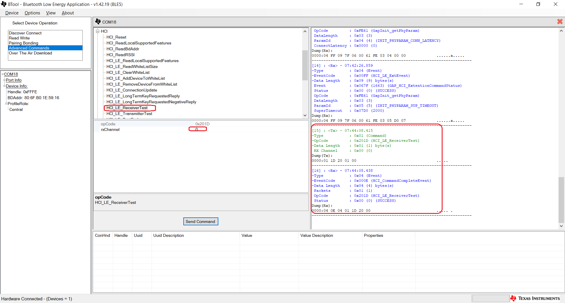
device enter Rx mode by sending the device a HCI_LE_ReceiverTest command.
 Figure 3-7 Set
HCI_LE_ReceiverTest
Figure 3-7 Set
HCI_LE_ReceiverTest“rxChannel” is the test channel.
- On Tx
side, configure the expected packets by sending the device a
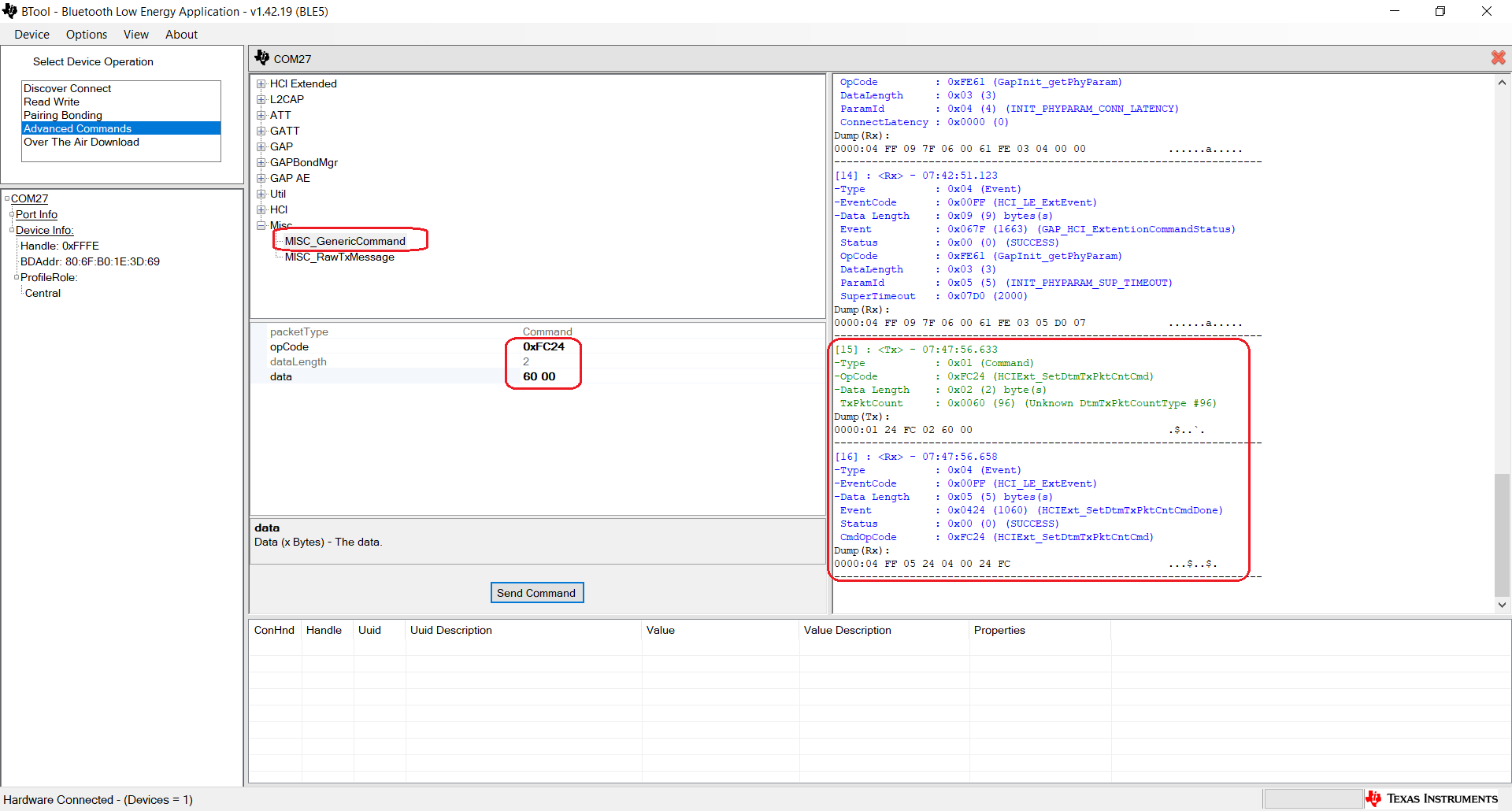
MISC_GenericCommand.
 Figure 3-8 Set
MISC_GenericCommand
Figure 3-8 Set
MISC_GenericCommandopcode: 0xFC24
data: <the length to be transmitted in hex format>
above example “60 00” means 0x0060
data Length: no need to input
- On Tx
side, let CC26xx/CC13xx device start to transmit packets by sending the device a
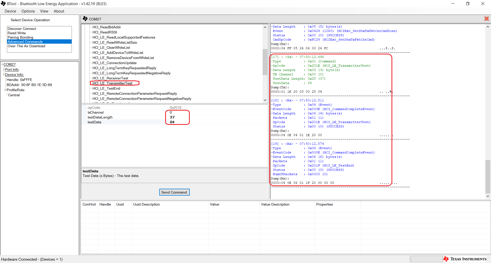
HCI_LE_Transmitter_Test command.
 Figure 3-9 Set
HCI_LE_Transmitter_Test
Figure 3-9 Set
HCI_LE_Transmitter_TesttxChannel: test channel, need to be the same as Rx side
testDataLength: length of payload bytes in each test packet, which can be any value from 0x00 to 0x25
testData: code for the type of data in the packet payload. The following values can be used
- 0x00 Pseudo-Random bit sequence 9
- 0x01 Pattern of alternating bits ‘11110000’
- 0x02 Pattern of alternating bits ‘10101010’
- 0x03 Pseudo-Random bit sequence 15
- 0x04 Pattern of All ‘1’ bits
- 0x05 Pattern of All ‘0’ bits
- 0x06 Pattern of alternating bits ‘00001111’
- 0x07 Pattern of alternating bits ‘0101’
- On Rx
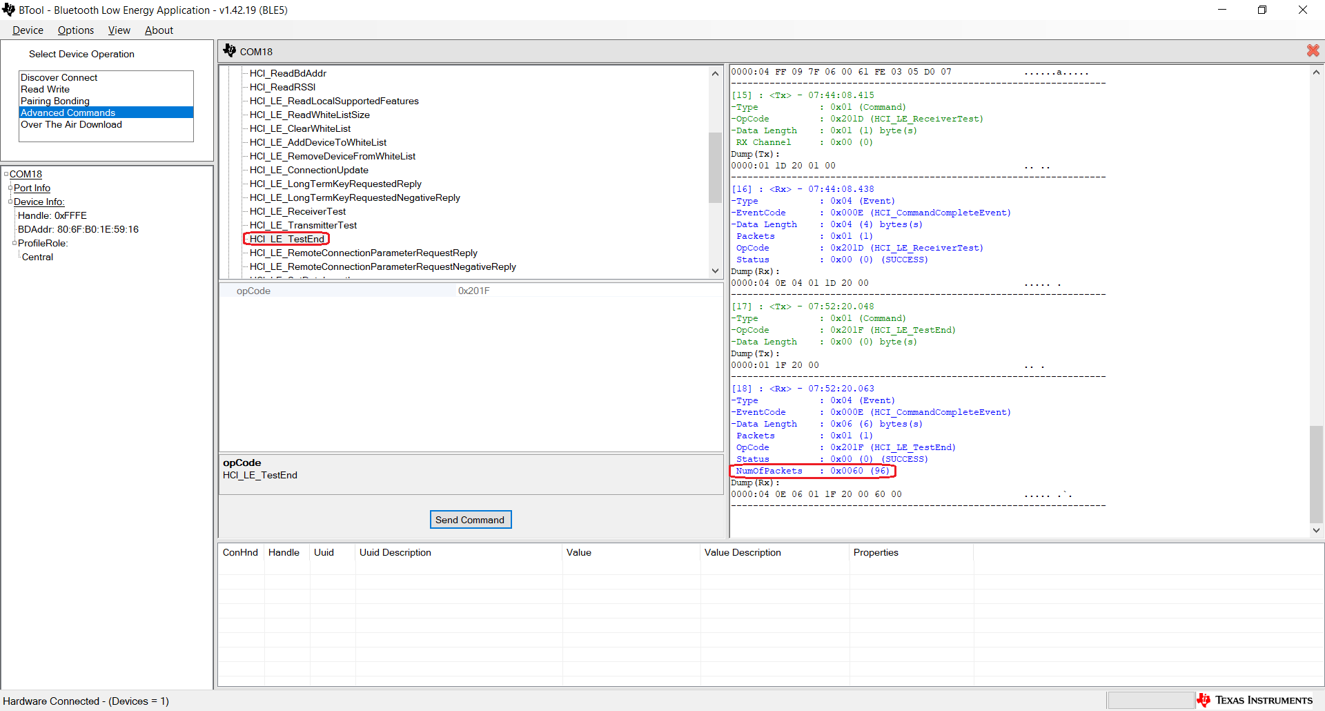
side, after finishing test, by sending the “HCI_LE_TestEnd” to get test
summary.
 Figure 3-10 Set
HCI_LE_TestEnd
Figure 3-10 Set
HCI_LE_TestEndNumberOfPackets: Total number of received packets