SWRA759 November 2022
3.2 Hardware Connection
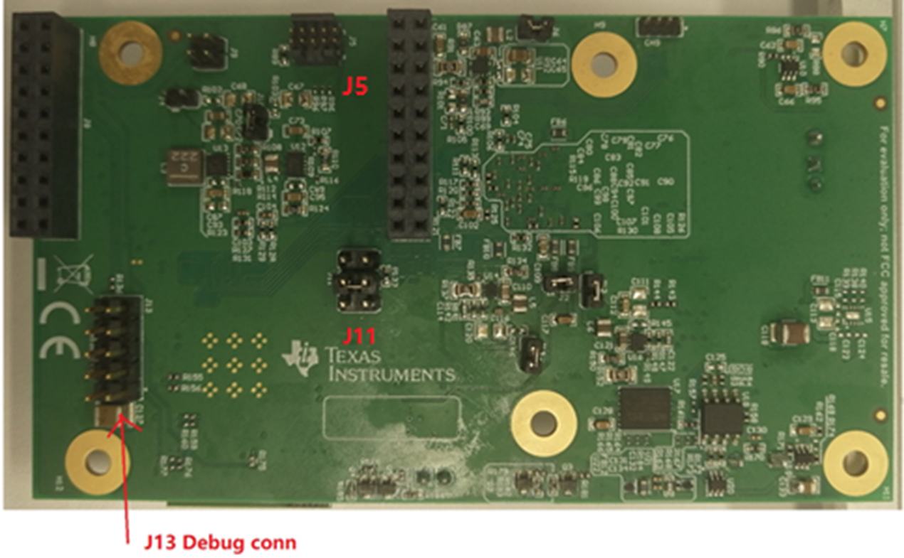
- Short J11.3 and J11.4 with a
jumper in order to enable download function via UART.
 Figure 3-1 J11 Connector
 - Connect J13 to CC3235EVM board UART pin according to the Connections Between CC32xx LaunchPad™ and Wireless Camera Module (J13 Connector) figure in the Design Guide: TIDA-010224 Low-Power Wireless Camera Reference Design for Extended Battery Life.
- Connect J5 to CC3235EVM board’s
J7(XDS10 OUT) connector with a JTAG cable.
 Figure 3-2 PCB Connector
 - Connect the PC to the camera board and the CC3235EVM board with the 2x USB cable. Power on these two boards.