SWRS096D December 2012 – April 2015 CC2538
PRODUCTION DATA.
- 1Device Overview
- 2Revision History
- 3Device Comparison
- 4Terminal Configuration and Functions
-
5Specifications
- 5.1 Absolute Maximum Ratings
- 5.2 ESD Ratings
- 5.3 Recommended Operating Conditions
- 5.4 Electrical Characteristics
- 5.5 General Characteristics
- 5.6 RF Receive Section
- 5.7 RF Transmit Section
- 5.8 32-MHz Crystal Oscillator
- 5.9 32.768-kHz Crystal Oscillator
- 5.10 32-kHz RC Oscillator
- 5.11 16-MHz RC Oscillator
- 5.12 RSSI/CCA Characteristics
- 5.13 FREQEST Characteristics
- 5.14 Frequency Synthesizer Characteristics
- 5.15 Analog Temperature Sensor
- 5.16 ADC Characteristics
- 5.17 Control Input AC Characteristics
- 5.18 DC Characteristics
- 5.19 USB Interface DC Characteristics
- 5.20 Thermal Resistance Characteristics for RTQ Package
- 6Applications, Implementation, and Layout
- 7Device and Documentation Support
- 8Mechanical Packaging and Orderable Information
6 Applications, Implementation, and Layout
NOTE
Information in the following applications sections is not part of the TI component specification, and TI does not warrant its accuracy or completeness. TI’s customers are responsible for determining suitability of components for their purposes. Customers should validate and test their design implementation to confirm system functionality.
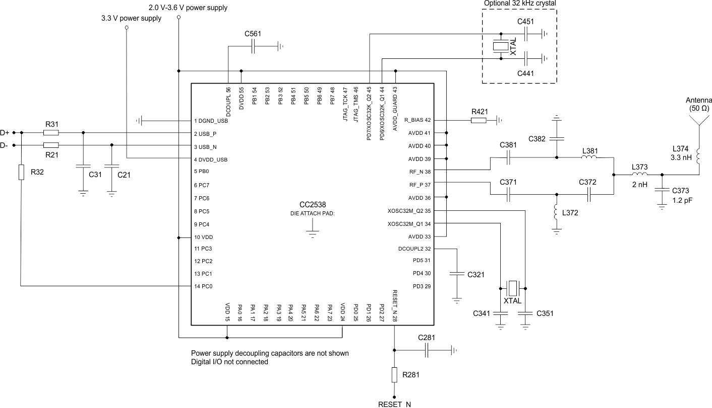
Few external components are required for the operation of the CC2538xFnn. Figure 6-1 is a typical application circuit. For a complete USB reference design, see the CC2538xFnn product page on www.ti.com. Table 6-1 lists typical values and descriptions of external components. The USB_P and USB_N pins require series resistors R21 and R31 for impedance matching, and the D+ line must have a pullup resistor, R32. The series resistors should match the 90-Ω ±15% characteristic impedance of the USB bus. Notice that the pullup resistor and DVDD_USB require connection to a voltage source between 3 V and 3.6 V (typically 3.3 V). To accomplish this, it is recommend to connect the D+ pull-up to a port/pin that does not have an internal pullup (that is, PC0..3), instead of connecting it directly to a 3.3 V supply (that is, software control of D+ pullup recommended).
Table 6-1 Overview of External Components (Excluding Supply Decoupling Capacitors)
| Component | Description | Value |
|---|---|---|
| C21 | USB D– decoupling | 47 pF |
| C31 | USB D+ decoupling | 47 pF |
| C341 | 32-MHz xtal-loading capacitor | 12 pF |
| C351 | 32-MHz xtal-loading capacitor | 12 pF |
| C371 | Part of the RF matching network | 18 pF |
| C381 | Part of the RF matching network | 18 pF |
| C382 | Part of the RF matching network | 1 pF |
| C372 | Part of the RF matching network | 1 pF |
| C441 | 32-kHz xtal-loading capacitor | 22 pF |
| C451 | 32-kHz xtal-loading capacitor | 22 pF |
| C561 | Decoupling capacitor for the internal digital regulator | 1 µF |
| C321 | Decoupling capacitor for the internal digital regulator | 1 µF |
| C281 | Filter capacitor for reset line | 1 nF |
| L372 | Part of the RF matching network | 2 nH |
| L381 | Part of the RF matching network | 2 nH |
| R21 | USB D– series resistor | 33 Ω |
| R31 | USB D+ series resistor | 33 Ω |
| R32 | USB D+ pullup resistor to signal full-speed device presence | 1.5 kΩ |
| R281 | Filter resistor for reset line | 2.2 Ω |
| R421 | Resistor used for internal biasing | 56 kΩ |
6.1 Input, Output Matching
When using an unbalanced antenna such as a monopole, use a balun to optimize performance. One can implement the balun using low-cost, discrete inductors and capacitors. The recommended balun shown in Figure 6-1 consists of L372, C372, C382 and L381.
If a balanced antenna such as a folded dipole is used, omit the balun.
6.2 Crystal
The 32-MHz crystal oscillator uses an external 32-MHz crystal, XTAL1, with two loading capacitors (C341 and C351). See the 32-MHz Crystal Oscillator section for details. Calculate the load capacitance across the 32-MHz crystal by Equation 1.

XTAL2 is an optional 32.768-kHz crystal, with two loading capacitors (C441 and C451) used for the 32.768-kHz crystal oscillator. Use the 32.768-kHz crystal oscillator in applications where both low sleep-current consumption and accurate wake-up times are needed. Calculate the load capacitance across the 32.768-kHz crystal by Equation 2.

Use a series resistor, if necessary, to comply with the ESR requirement.
6.3 On-Chip 1.8-V Voltage-Regulator Decoupling
The 1.8-V on-chip voltage regulator supplies the 1.8-V digital logic. This regulator requires decoupling capacitors (C561, C321) and an external connection between them for stable operation.
6.4 Power-Supply Decoupling and Filtering
Optimum performance requires proper power-supply decoupling. The placement and size of the decoupling capacitors and the power supply filtering are important to achieve the best performance in an application. TI provides a recommended compact reference design for the user to follow.
6.5 References
- IEEE Std. 802.15.4-2006: Wireless Medium Access Control (MAC) and Physical Layer (PHY) Specifications for Low-Rate Wireless Personal Area Networks (LR-WPANs)
http://standards.ieee.org/getieee802/download/802.15.4-2006.pdf - CC2538xFnn User's Guide
- Universal Serial Bus Revision 2.0 Specification http://www.usb.org/developers/docs/usb_20_052709.zip
