SWRU622A August 2024 – September 2024 AWRL1432 , AWRL6432 , IWRL1432 , IWRL6432 , IWRL6432AOP
- 1
- Trademarks
- 1Introduction
- 2Basic Bootloader Flow
- 3Secondary Bootloader
- 4Warm Reset
- 5Relevant Registers
- 6Revision History
4.4.2.1 Setting Boot Vector to 0x0
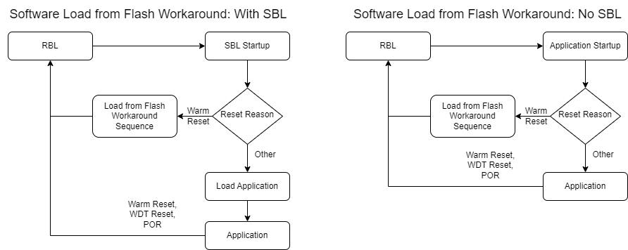
A software-based workaround to load the image from Flash is possible by modifying the jump address used in the warm reset flow. Proper care must also be taken to ensure that the FECSS (Front End Controller Subsystem) is in the correct state. A user must perform any necessary safety assessment of their own system to determine if this software-based workaround meets their needs. The flow of the workaround sequence is as follows:
 Figure 4-2 Software Load From Flash on a
Warm Reset
Figure 4-2 Software Load From Flash on a
Warm Reset- Gracefully power down FECSS and HWASS
- Power on FECSS
- Write Boot vector to TOP_PRCM:PC_REGISTER2[24:0] = 0
- Write boot vector parity to TOP_PRCM:PC_REGISTER1[15:12] = 0
- Disable image integrity check - TOP_PRCM:PC_REGISTER1[5:3] = 0
- Disable STC test - TOP_PRCM:PC_REGISTER1[8:6] = 0
- Trigger warm reset - TOP_PRCM:RST_SOFT_RESET[0] = 1
Execution re-enters the RBL after the warm reset in step 7 occurs, which starts execution as shown in Figure 2-1. The RBL determines the reset reason as invalid because the reset registers have been cleared. It assumes a POR because of this, and the application image is loaded from Flash once again. The application or SBL can continue as designed, until another reset occurs.
View the watchdog_reset example in the
MMWAVE-L-SDK under:
<SDK-Install-Directory>/examples/drivers/watchdog/watchdog_reset/
for the fully-coded sequence to perform the reload from flash.