SWRU622A August 2024 – September 2024 AWRL1432 , AWRL6432 , IWRL1432 , IWRL6432 , IWRL6432AOP
- 1
- Trademarks
- 1Introduction
- 2Basic Bootloader Flow
- 3Secondary Bootloader
- 4Warm Reset
- 5Relevant Registers
- 6Revision History
2.7.1 Booting From Serial Flash
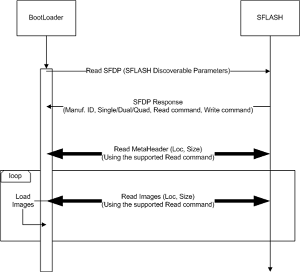
In functional mode, the bootloading of an image from the SDF is the first bootmode attempted by the bootloader (see Figure 2-3). If for some reason quad or dual read mode fails in this process, the RBL tries single mode.
 Figure 2-3 Image Load Sequence
This bootmode involves the following steps (taken care of by the ROM Bootloader):
- Pinmux the QSPI pins of the xWRLx432 device.
- QSPI is set up to operate at (system clock / 2) = (160/2) = 80MHz.
- The SFLASH discoverable parameters (SFDP) command is issued to retrieve the JEDEC compliant response, which includes information regarding the SFLASH capabilities and command set. When the SFDP response is received, the information is used to communicate with the SDF and further interpret the contents and load the images.
Key points:
- The ROM bootloader performs the read from the SDF, based on the highest capability mode (quad, dual, or single) as published by the SDF in response to the SFDP command.
- For SDF variants that support quad mode, the quad mode commands are issued; if the quad enable (QE) bit is not set, the communication fails. In such cases, the load flow assumes that the QE bit in the SDF is already set.
- Fallback images: the bootloader supports loading of images from
the following locations as a fallback mechanism if one of the images is
corrupted in the SDF. The locations of the images are:
- META IMG1(SDF offset – 0x0)
- META IMG2(SDF offset – 0x80000)
- META IMG3(SDF offset – 0x100000)
- META IMG4(SDF offset – 0x180000)
For image format details, see the AWRL6432, IWRL6432, AWRL1432, IWRL1432 Technical Reference Manual.