TIDT194 August 2020 – MONTH
6 Schematic and Assembly Diagram
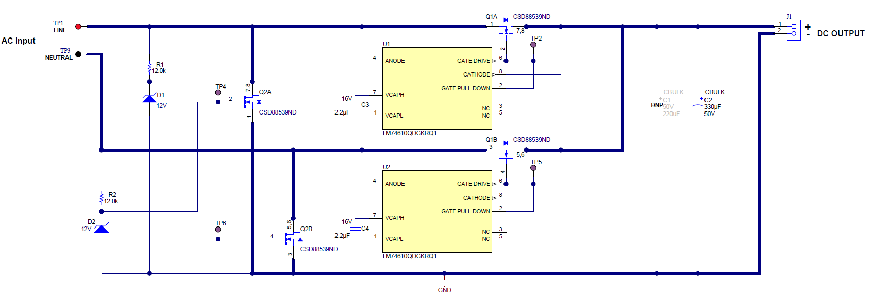
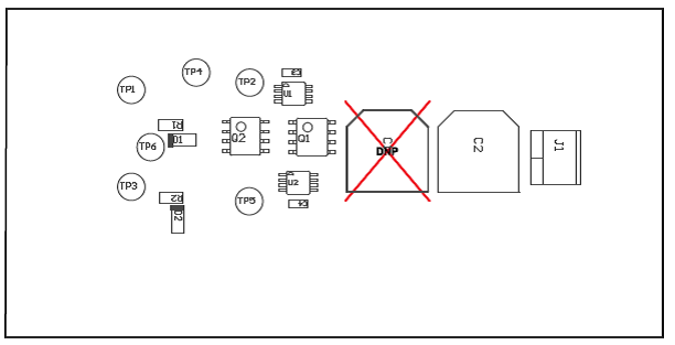
Figure 6-1 shows the PMP22504 schematic and Figure 6-2 illustrates the assembly diagram.
 Figure 6-1 PMP22504 Schematic
 Figure 6-2 PMP22504 Assembly Diagram
TIDT194 August 2020 – MONTH
Figure 6-1 shows the PMP22504 schematic and Figure 6-2 illustrates the assembly diagram.
 Figure 6-1 PMP22504 Schematic
 Figure 6-2 PMP22504 Assembly Diagram