TIDT194 August 2020 – MONTH
2 Design Description
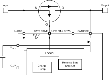
The LM74610-Q1 device is a controller device that can be used with an N-Channel MOSFET in a reverse polarity protection circuitry. It is designed to drive an external MOSFET to emulate an ideal diode rectifier when connected in series with a power source. A unique advantage of this scheme is that it is not referenced to ground and thus has Zero IQ. The LM74610-Q1 controller provides a gate drive for an external N-Channel MOSFET and a fast response internal comparator to discharge the MOSFET gate in the event of reverse polarity. This fast pulldown feature limits the amount and duration of reverse current flow if opposite polarity is sensed.
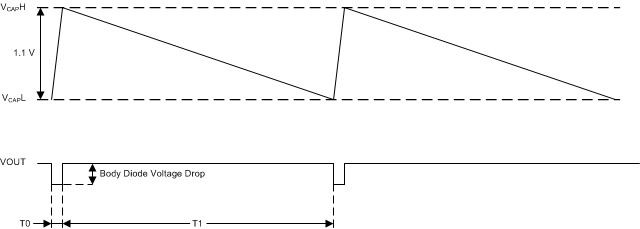
The LM74610-Q1 controller does not have GND pin. During start up, it depends on the forward drop of the body diode to generate the charge pump voltage whenever a load is connected. The charge pump has a kind of hysteretic control, where it monitors charge pump (VCAP) voltage for high (VCAP-H) and low thresholds (VCAP-L). There will be a phase when gate drive is disabled when VCAP voltage reaches VCAP-L threshold and re-enabled when VCAP voltage is again charged to VCAP-H (see Figure 2-1 and Figure 2-2). For additional information, see the Feature Description section of the LM74610-Q1 Zero IQ Reverse Polarity Protection Smart Diode Controller Data Sheet.
 Figure 2-1 LM74610-Q1 Functional Block
Diagram
 Figure 2-2 VCAP Charging and
Discarding by the Charge Pump
Figure 2-2 VCAP Charging and
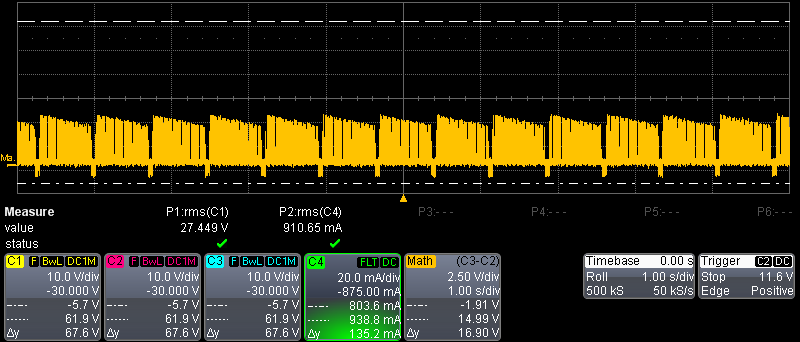
Discarding by the Charge PumpFigure 2-3 highlights the Vgate illustrating VCAP discharging cycles.
 Figure 2-3 Vgate Illustrating VCAP Discharging
Cycles