TIDT200 September 2020
3.2 Output Voltage Ripple
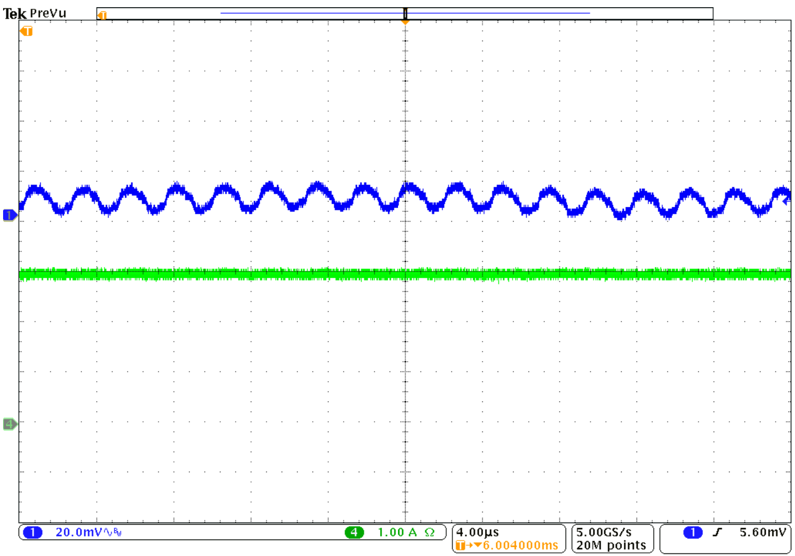
Output voltage ripple is shown in the following figures.

| CH1: VPA_BUS, | CH4: IPA_BUS |

| CH1: VPB_BUS | CH4: IPB_BUS |
TIDT200 September 2020
Output voltage ripple is shown in the following figures.

| CH1: VPA_BUS, | CH4: IPA_BUS |

| CH1: VPB_BUS | CH4: IPB_BUS |