TIDT219 February   2023


  1.   Description
  2.   Features
  3.   Applications
  4. 1Test Prerequisites
    1. 1.1 Voltage and Current Requirements
    2. 1.2 Dimensions
  5. 2Testing and Results
    1. 2.1 Efficiency Graphs
    2. 2.2 Efficiency Data
    3. 2.3 Thermal Images
    4. 2.4 Bode Plots
    5. 2.5 Electromagnetic Interference (EMI)
  6. 3Waveforms
    1. 3.1 Switching
    2. 3.2 Output Voltage Ripple
    3. 3.3 Short-Circuit Protection
    4. 3.4 Load Transients
    5. 3.5 Start-up Sequence

Thermal Images

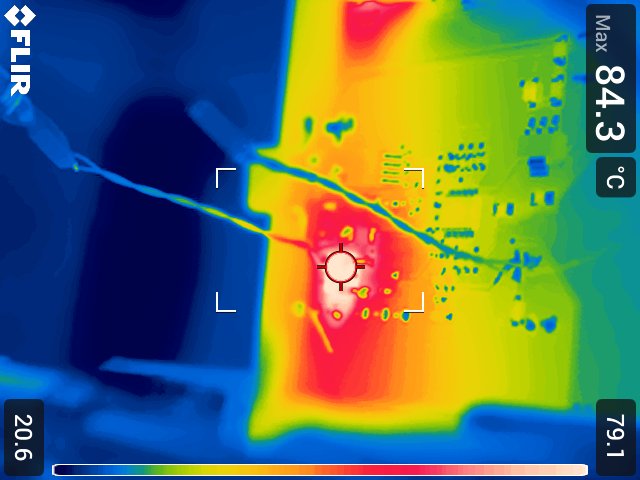
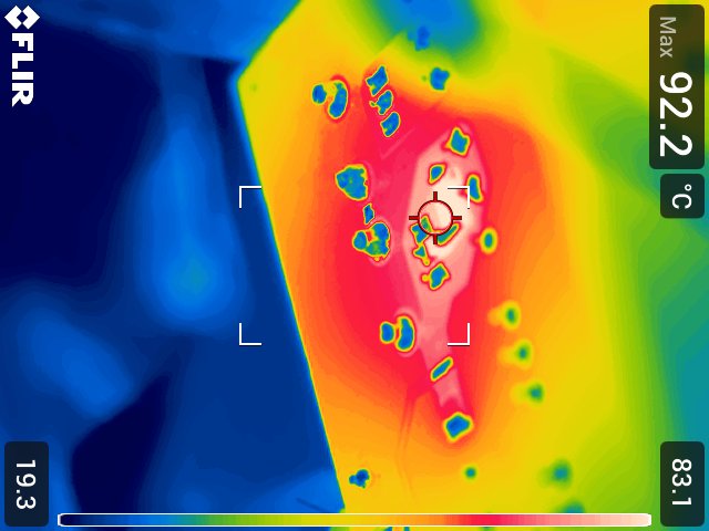
The following thermal images show a top view and bottom view of the board. The ambient temperature is 25ºC with no additional air flow. The supply is fully loaded for 30 minutes to reach thermal equilibrium.
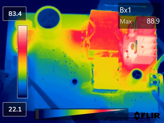
GUID-20221014-SS0I-LFTV-LLHZ-XR6RBXN3LCBX-low.jpg
Bx1 – D5, Rectifier diode
Figure 2-2 Top Side
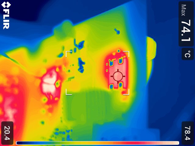
GUID-20221014-SS0I-592J-TZ4Q-3G5PNFBZ7ZPH-low.jpgFigure 2-4 D1 - Bridge Rectifier
GUID-20221014-SS0I-PF9M-MRVB-Q1XLNQQGDBS6-low.jpgFigure 2-3 Q3 - Primary FET
GUID-20221014-SS0I-CWDX-LBZQ-CM39CNNH2WD9-low.jpgFigure 2-5 R101 - Snubber Resistor