TIDT232 September 2021
8.2 EMI Scans - 4x UCC12050, 5 VOUT
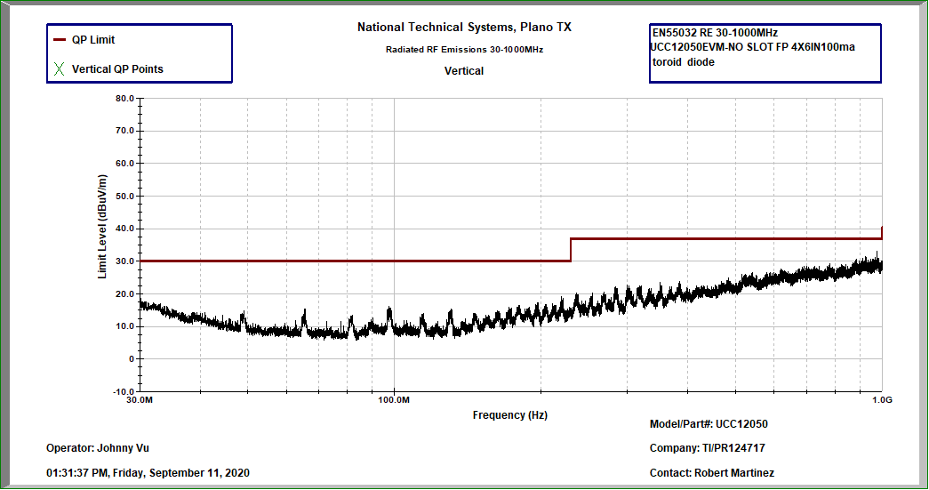
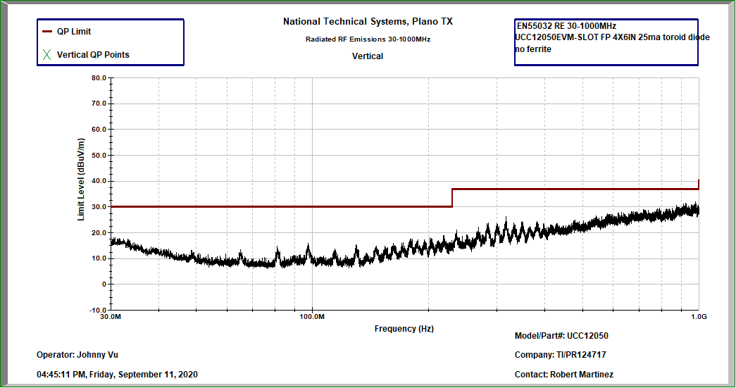
The test results shown in Figure 8-5 through Figure 8-8, demonstrate the radiated emissions for a four, 5-V, UCC12050 converters operating simultaneously at 25% load and 100% load. Cases where the receiving antenna is orientated horizontally and vertically are labeled accordingly. Figure 8-7 and Figure 8-8 show the effect of removing all ferrite beads and should be considered as the worst case without any PCB, EMI mitigation.
 Figure 8-5 Horizontal, Ferrite Beads L1-L8, –5.06 dB (975 MHz), 100% Load (500 mW)
 Figure 8-6 Vertical, Ferrite Beads L1-L8, –3.97 dB (975 MHz), 100% Load (500 mW)
 Figure 8-7 Horizontal, no Ferrite Beads, –0.11 dB (544 MHz), 25% Load (125 mW)
 Figure 8-8 Vertical, no Ferrite Beads, –4.83 dB (980 MHz), 25% Load (125 mW)