TIDT237 December 2022 TPS73801-SEP
3.2 Current Limit
The following figures show a load step being applied from 2.1 A to 3.5 A. The current ramps up, hits current limit, and output drops followed by hiccup mode. Once the load step goes down to 2.1 A the output recovers with soft start.
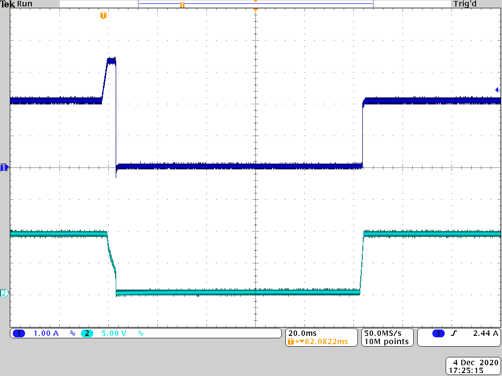 Figure 3-37 Load Step, 13.2
VIN, 25°C
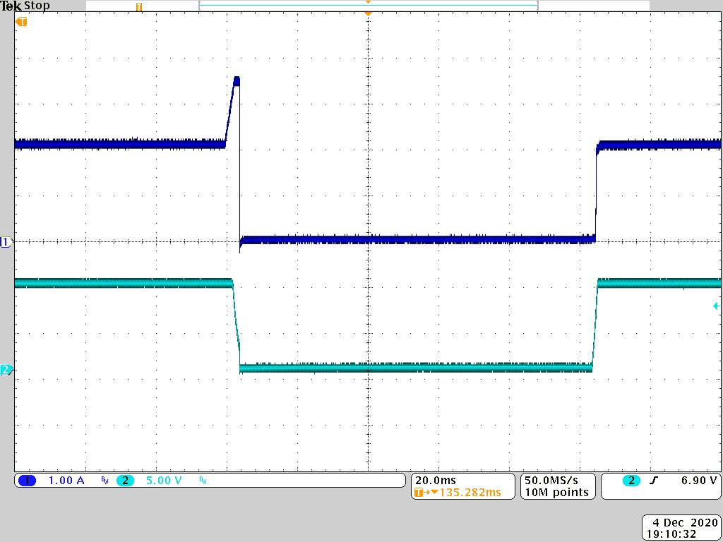 Figure 3-38 Load Step, 13.2
VIN, –30°C
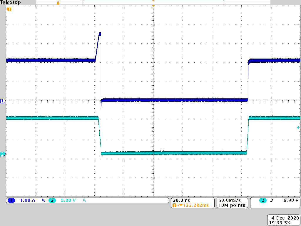 Figure 3-39 Load Step, 13.2
VIN, 85°C
Figure 3-39 Load Step, 13.2
VIN, 85°CIn Figure 3-40 through Figure 3-42, the current limit trip point shifts as the load is increased to above the limit.
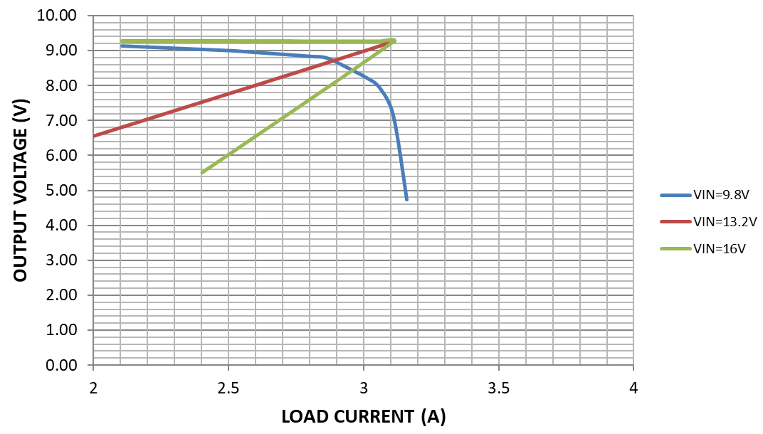 Figure 3-40 LM63625 Output Voltage vs Load
Current, VOUT = 9.3 V, Ta = 85°C
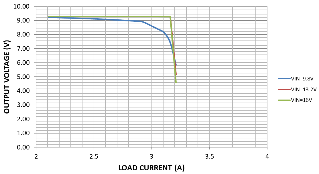 Figure 3-41 LM63625 Output Voltage vs Load
Current, VOUT = 9.3 V, Ta = 25°C
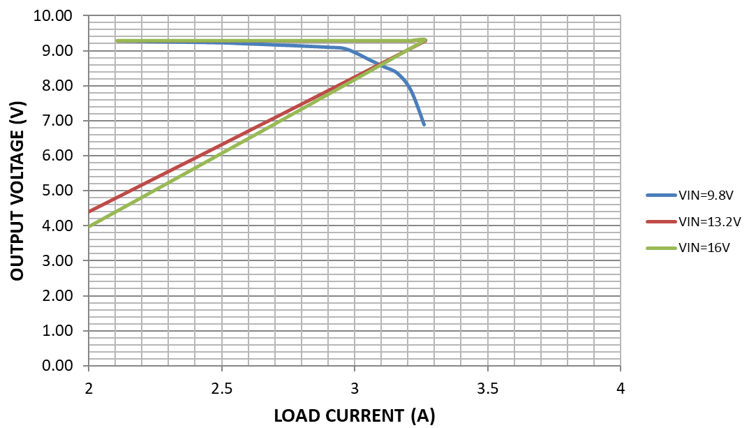 Figure 3-42 LM63625 Output Voltage vs Load
Current, VOUT = 9.3 V, Ta = –30°C