TIDT240 October   2021


  1. 1Description
  2. 2Test Prerequisites
    1. 2.1 Voltage and Current Requirements
    2. 2.2 Required Equipment
    3. 2.3 Considerations
    4. 2.4 Dimensions
    5. 2.5 Signal Descriptions
  3. 3Testing and Results
    1. 3.1 Efficiency Graphs
    2. 3.2 Efficiency Data
    3. 3.3 Voltage Regulation Graphs
    4. 3.4 Cross-Loading Performance
    5. 3.5 Cross-Loading Performance Data
  4. 4Waveforms
    1. 4.1 Switching
    2. 4.2 Output Voltage Ripple
    3. 4.3 Load Transients
    4. 4.4 Start-up Sequence

Start-up Sequence

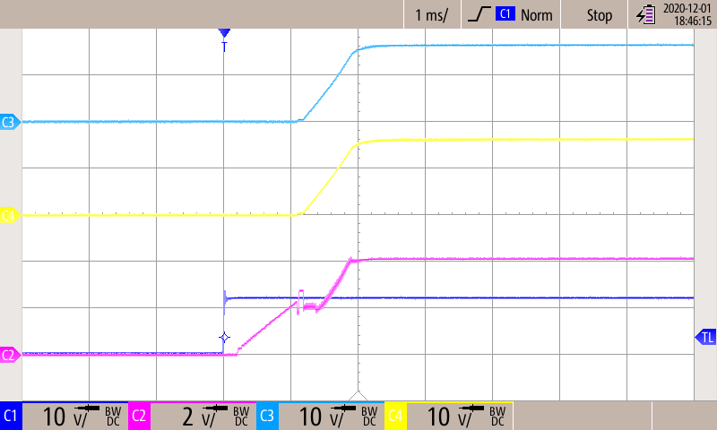
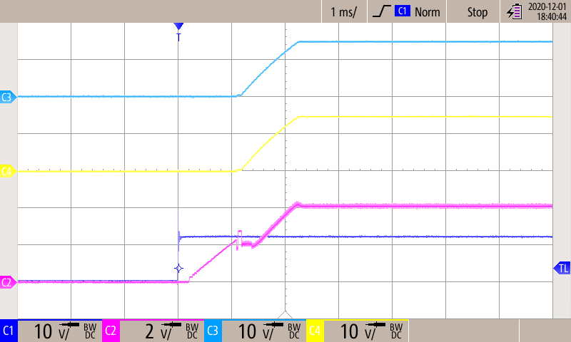
The oscilloscope screenshot in Figure 4-8 shows start-up to the no-load condition. Note that the glitch at the output of the buck converter happens when the SN6505-Q1 starts switching. Figure 4-9 illustrates how soft-start (SN6505B-Q1) improves this behavior. Both of the waveforms are taken using a Scope Rider handheld oscilloscope with isolated channels.
GUID-20210721-CA0I-P3NL-MVNZ-3HRMXNQGKLBJ-low.png
CH1 - VIN, CH2 - Vout-bck, CH3 - VOUT1, CH4 - VOUT2
Figure 4-8 Start-up to No-Load Condition
GUID-20210721-CA0I-FH1W-KWMK-4QNQWXCFQHLS-low.png
CH1 - VIN, CH2 - Vout-bck, CH3 - VOUT1, CH4 - VOUT2
Figure 4-9 Start-up to 2 × 150-Ω Load