TIDT293 October 2022
5.1 Wiring Inductance
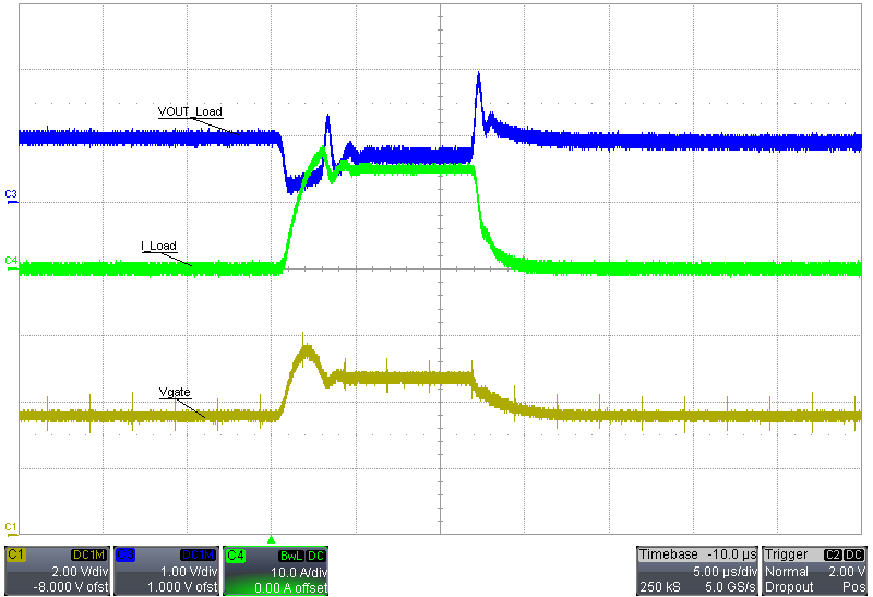
When adjusting to a lower voltage, the load-step current is limited by the wiring inductance and slew rate of the setup. The following scope plot is a 1-A to 10-A load transient for a 1-V output. There is about a 0.7 V voltage drop, leaving 0.3 V for the MOSFET and sense resistor. Use short wires soldered directly to the load step board to reduce wiring inductance. The results in the following waveform use a PSMN008-75B MOSFET in the 125-A variant.
 Figure 5-1 Wiring Inductance Voltage Drop 1 A to 10 A, 1-V Output Load Transient
A larger load step causes the MOSFET voltage to collapse, resulting in an abnormal load transient. The following scope plot is a 1-A to 15-A load transient for a 1-V output.
 Figure 5-2 Wiring Inductance Voltage Drop 1 A to 15 A, 1-V Output Load Transient