TIDT319
December 2022
Description
Features
Applications
1
Test Prerequisites
1.1
Voltage and Current Requirements
1.2
Considerations
1.3
Dimensions
2
Testing and Results
2.1
Efficiency Graph
2.2
Loss Graph
2.3
Load Regulation
2.4
Thermal Images
2.4.1
Summary, Hottest Spot High-Side FET Q6, NVMFS5C645NL
2.4.2
Thermal Images
2.4.3
Thermal Mechanics
2.5
Bode Plots
2.5.1
Bode Plot Summary, Loop Bandwidth 16 kHz
2.5.2
24-V Input Voltage
2.5.3
36-V Input Voltage
2.5.4
48-V Input Voltage
3
Waveforms for 2 × LM5143A-Q1 in Four Phase Configuration and Interleaved Operation
3.1
Switching
3.1.1
Overview of the Four Switching Phases
3.1.1.1
24-V Input Voltage
3.1.1.2
36-V Input Voltage
3.1.1.3
48-V Input Voltage
3.1.2
Low-Side FET
3.1.2.1
Switch Node to GND
3.1.2.2
Low-Side FET Gate to GND
3.1.3
High-Side FET
3.1.3.1
Switch Node to VIN
3.1.3.2
High-Side FET Gate to Switch Node
3.2
Output Voltage Ripple
3.3
Input Voltage Ripple
3.3.1
Board Input
3.3.1.1
24-V Input Voltage
3.3.1.2
36-V Input Voltage
3.3.1.3
48-V Input Voltage
3.3.2
Power Stage Input, No Input Filter
3.3.2.1
24-V Input Voltage
3.3.2.2
36-V Input Voltage
3.3.2.3
48-V Input Voltage
3.4
Load Transients
3.4.1
Load Transient 10 A to 50 A (80 %)
3.4.2
Load Transient 5 A to 50 A (90 %)
3.5
Start-Up Sequence
3.6
Shutdown Sequence
A Individual Adjusting of the Rising Edge and Falling Edge With LM5143A
A.1 2.21-Ω High and 4.75-Ω Low Resistor in Before Gate of the High-Side FET
A.2 2 × 4.75-Ω Resistors in Before Gate of the High-Side FET
B Measurements Across the Low-Side FETs to Check at All Four Phases
B.1 FET Q3
B.2 FET Q4
B.3 FET Q7
B.4 FET Q8
C ON Demand – Assembly of Thermal Interface
C.1 Thermal Interface Example
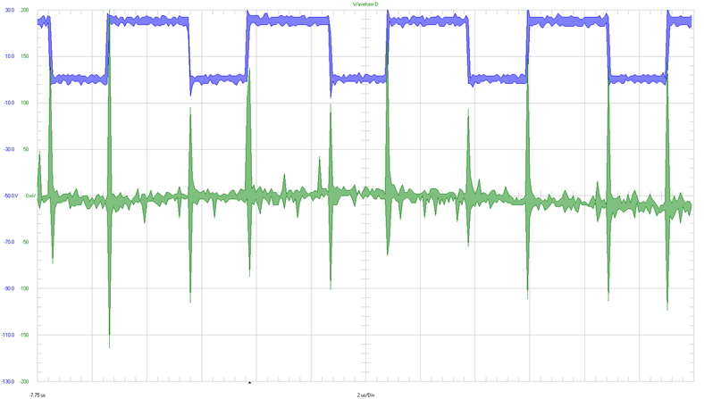
3.3.1.1
24-V Input Voltage
SW2 ⇒ 20 V / div
V
IN
⇒ 50 mV / div
2 µs / div
Full bandwidth
Figure 3-9
Voltage Ripple: Board Input (AC Coupled) at 24-V Input Voltage