TIDT332 May 2024
3.2 Bidirectional Transient
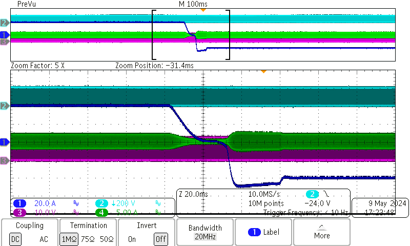
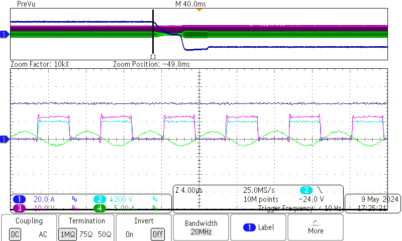
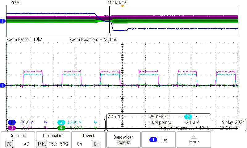
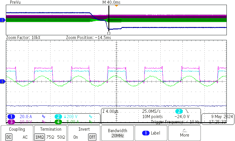
Figure 3-13 through Figure 3-16 show the bidirectional current transition from +40A to –40A on the LV side.
- Channel 1 (dark blue) is the current on the LV side
- Channel 2 (light blue) is the Vds of GaN on the HV side and high bridge
- Channel 3 (purple) is the Vds of MOS on the LV side
- Channel 4 (green) is the resonant current on the HV side
 Figure 3-13 Current Transient From
+40A (Forward) to 40A (Backward), Overview
 Figure 3-15 Current Transient From
+40A (Forward) to –40A (Backward), Zoom in at +40A
 Figure 3-14 Current Transient From 40A
(Forward) to –40A (Backward), Zoom in at 0A
 Figure 3-16 Current Transient From 40A
(Forward) to –40A (Backward), Zoom in at –40A