TIDT347A November 2023 – October 2024
3.2 Switching Waveform
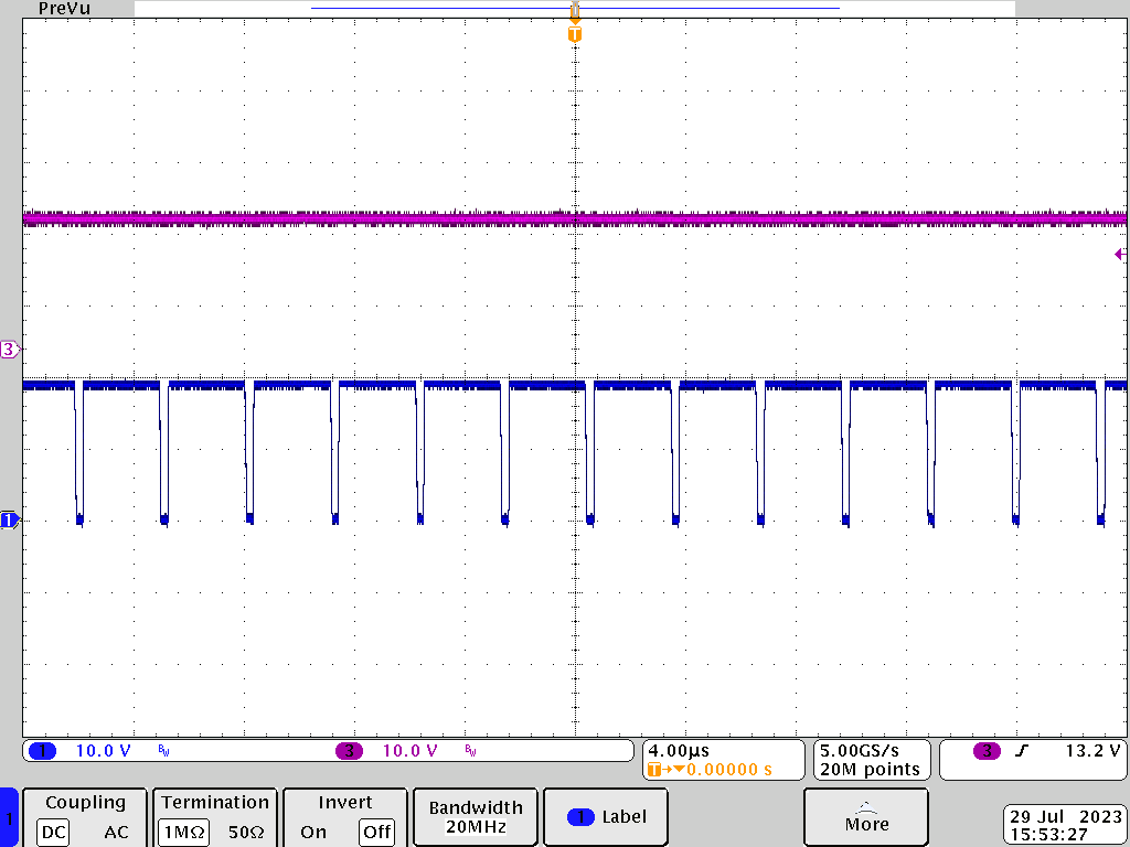
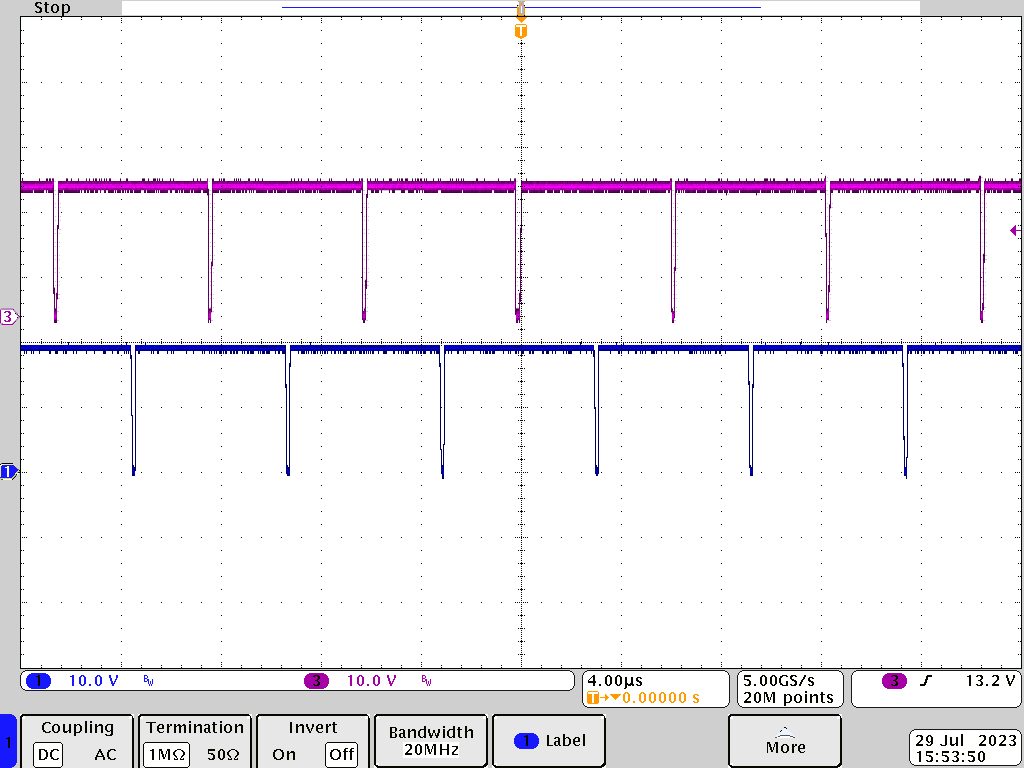
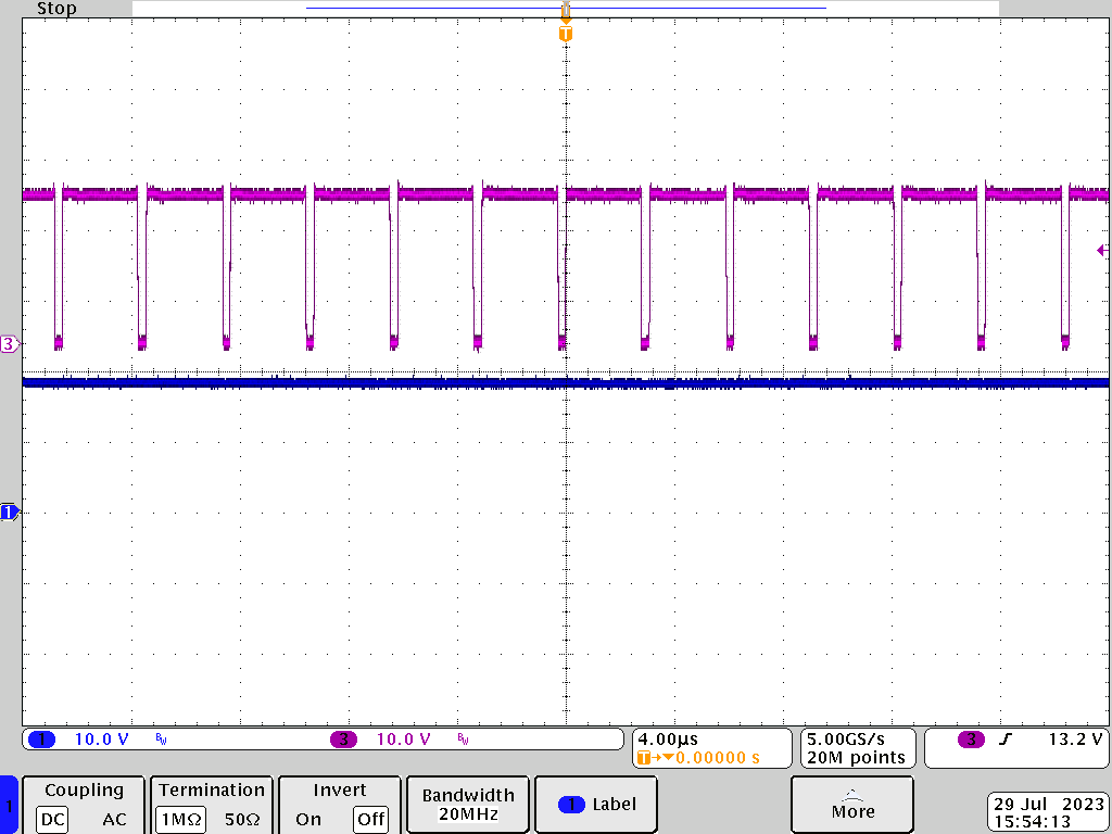
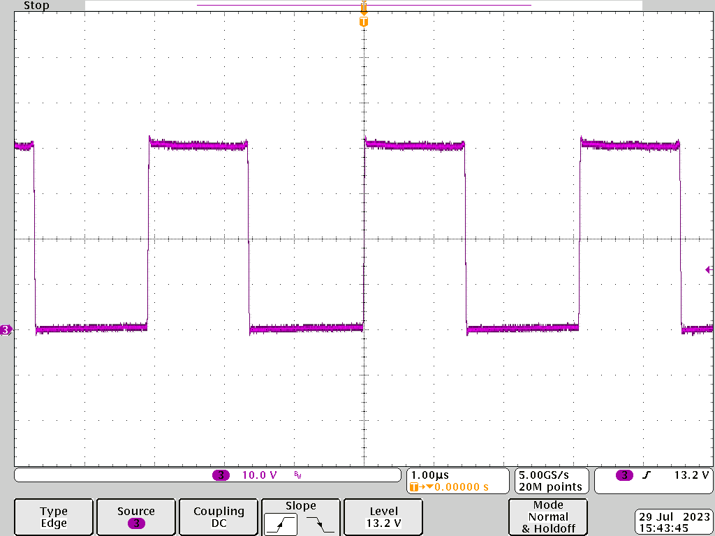
Figure 3-5 through Figure 3-8 show the power stage waveform at different working modes in the BQ25756 device among buck mode, buck-boost mode, and boost mode with seamless transition. The switching frequency is set to 300kHz.

Blue: buck leg SW point, Purple:
boost leg SW point
Figure 3-5 Buck Mode
Blue: Buck Leg SW point, Purple:
Boost leg SW Point
Figure 3-6 Buck-Boost Mode
Blue: buck leg SW point, Purple:
boost leg SW point
Figure 3-7 Boost Mode Figure 3-8 Switching Leg Waveform at Vsys
= 20V, Vbat = 40V Fast Charging Mode, fSW = 300kHz