TIDT352 October 2023
3.2 Load Transients
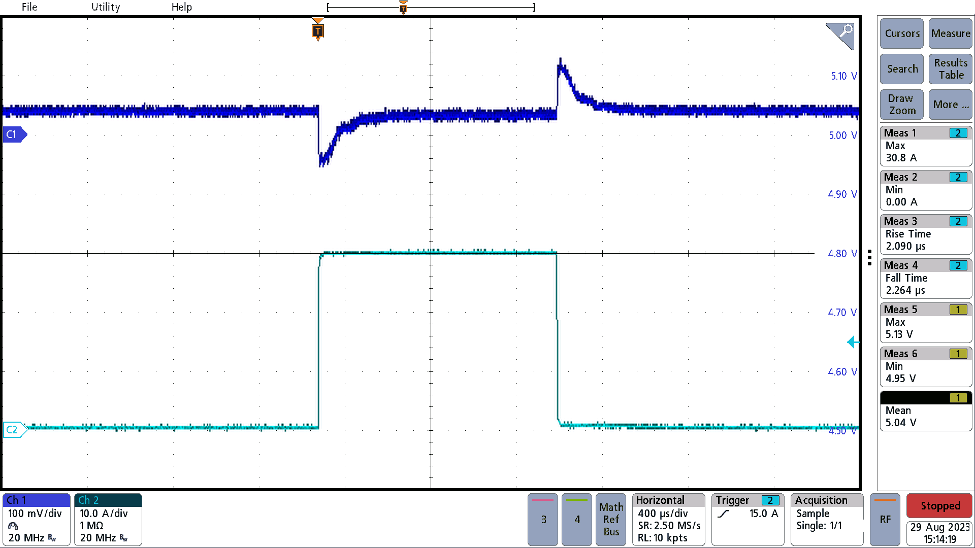
Figure 3-15 represents load transient 1 at 24 VIN with a 15-A steady-state load in parallel (not captured by the current probe), thus the images show a step and dump between 0 A and 30 A. Load transient 1 exhibits a step response, starting from a load of 15 A to 45 A, followed by a load dump from 45 A to 15 A. The load change time for both transitions is approximately 2 µs. The undershoot and overshoot for each is around 2% or 100 mV. For all images, the top trace represents VOUT, while the bottom represents IOUT.
 Figure 3-2 Load Transient 1
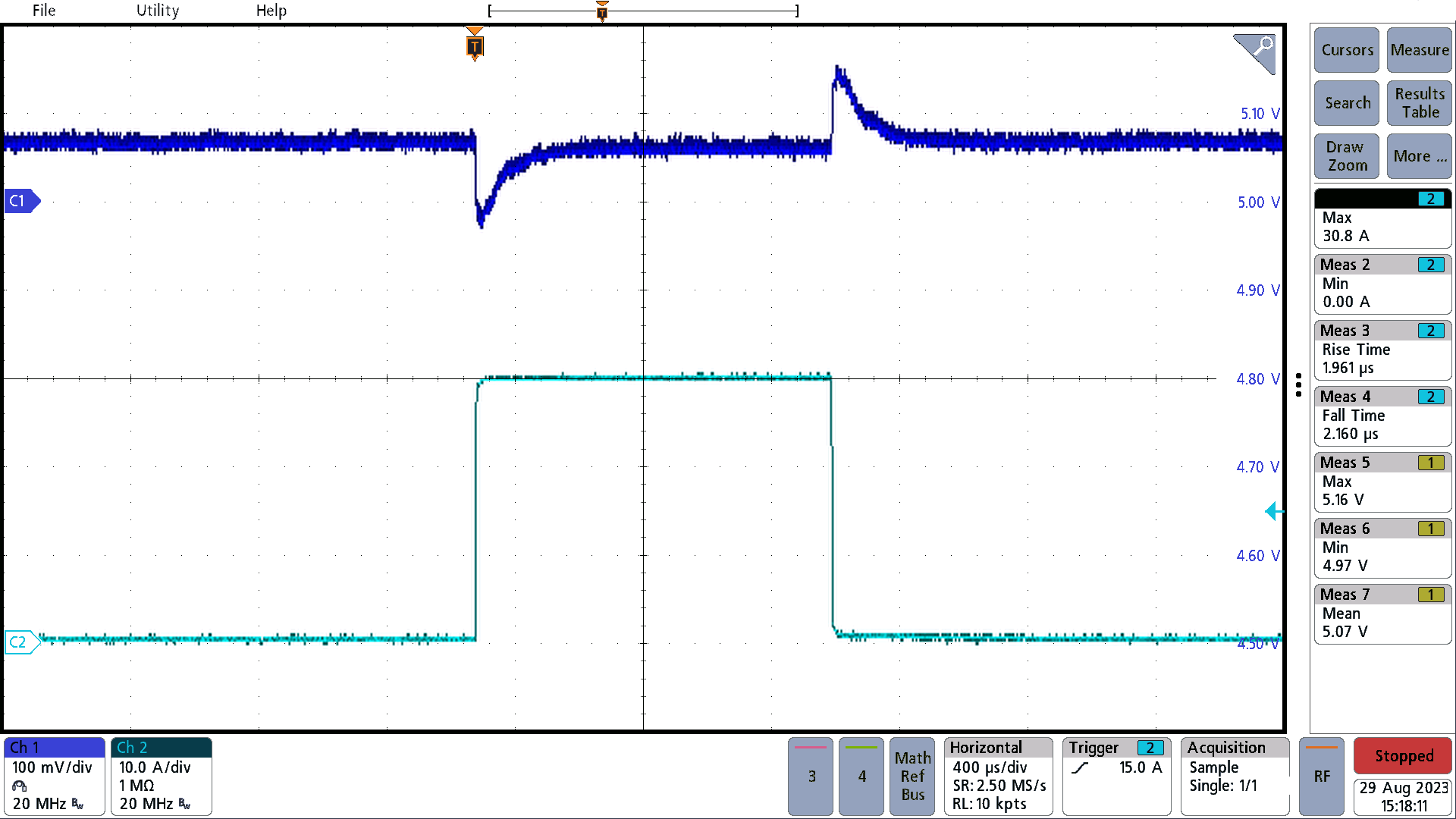
Figure 3-3 illustrates the load transient 2 at 48 VIN with a 15-A load in parallel, thus the images show a step and dump between 0 A and 30 A. Load transient 2 exhibits a step response, starting from a load of 15 A to 45 A, followed by a load dump from 45 A to 15 A. The load change time for both transitions is approximately 2 µs. Both the overshoot and undershoot measure to be about 100 mV.
 Figure 3-3 Load Transient 2