TIDT352 October 2023
2.3 Thermal Images
The thermal images presented in Figure 2-3 and Figure 2-4 were taken with a load of 60 A at steady-state and with a fan blowing on the hardware.
Figure 2-3 has an input voltage of 24 V, to which both the low-side FETs experienced a rise of about 74°C above the ambient room temperature of 21°C to 23°C. Figure 2-4 has an input voltage of 48 V, to which the low-side FET reaches a temperature of 112°C, measured relative to the ambient room temperature of 21°C to 23°C.
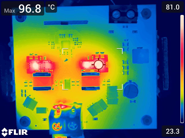 Figure 2-3 24-VIN, 60-A
Thermal Image With Fan
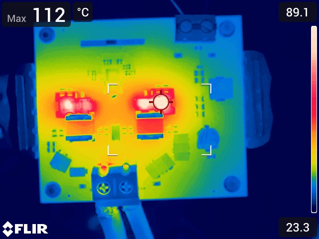 Figure 2-4 48-VIN, 60-A
Thermal Image With Fan
Figure 2-4 48-VIN, 60-A
Thermal Image With FanThe thermal images shown in Figure 2-5 and Figure 2-6 were taken with a load of 40 A at steady-state and with a fan blowing on the hardware.
Figure 2-5 has an input voltage of 24 V, to which both the low-side FETs experienced a rise of about 32°C above the ambient room temperature of 21°C to 23°C. Figure 2-6 has an input voltage of 48 V, to which the low-side FET reaches a temperature of 69°C, measured relative to the ambient room temperature of 21°C to 23°C.
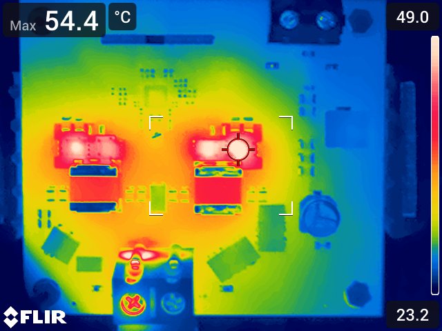 Figure 2-5 24-VIN, 40-A
Thermal Image With Fan
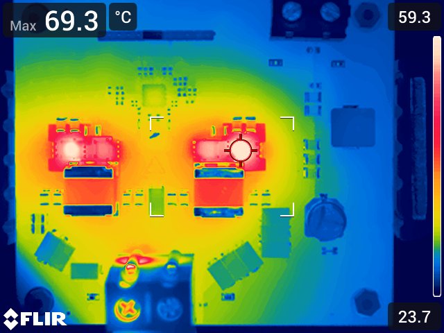 Figure 2-6 48-VIN, 40-A
Thermal Image With Fan
Figure 2-6 48-VIN, 40-A
Thermal Image With FanThe thermal images shown in Figure 2-7 and Figure 2-8 were taken with a load of 30 A at steady-state and without a fan blowing on the hardware.
With an input voltage of 24 V, the thermal image displayed in Figure 2-7 shows the low-side FET reaching 76°C. With an input voltage of 48 V, the thermal image displayed in Figure 2-8 shows the low-side FET reaching 101°C. Both were measured relative to the ambient room temperature of 21°C to 23°C.
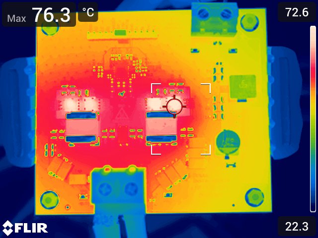 Figure 2-7 24-VIN, 30-A
Thermal Image With No Fan
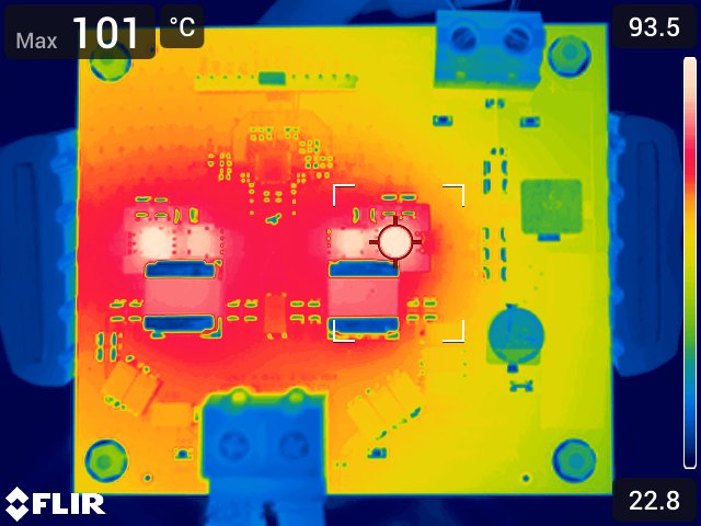 Figure 2-8 48-VIN, 30-A
Thermal Image With No Fan
Figure 2-8 48-VIN, 30-A
Thermal Image With No FanWith strong airflow or an efficient cooling system in place, the board can perform when operating up to full load in steady-state.