TIDT368 August   2024


  1.   1
  2.   Description
  3.   Features
  4.   Applications
  5. 1Test Prerequisites
    1. 1.1 Voltage and Current Requirements
    2. 1.2 Required Equipment
    3. 1.3 Considerations
    4. 1.4 Dimensions
    5. 1.5 Test Setup
  6. 2Testing and Results
    1. 2.1 Efficiency Graphs
    2. 2.2 Efficiency Data
    3. 2.3 Output Voltage Regulation Graphs
    4. 2.4 Thermal Images
    5. 2.5 EMI
  7. 3Waveforms
    1. 3.1 Switching
    2. 3.2 Output Voltage Ripple
    3. 3.3 Load Transients
    4. 3.4 Output Voltage Start-Up Sequence
    5. 3.5 Overcurrent Protection (OCP)
    6. 3.6 Short-Circuit Protection (SCP)

Load Transients

Figure 3-13 and Figure 3-14 show load transient waveforms between 0% and 100% at 115VAC and 230VAC.
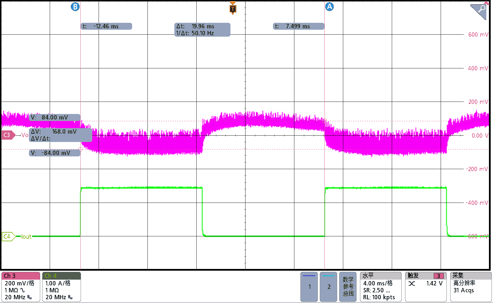
PMP41015 Output Voltage Start-Up Waveform at 85VAC,
                        Full LoadFigure 3-13 Output Voltage Start-Up Waveform at 85VAC, Full Load
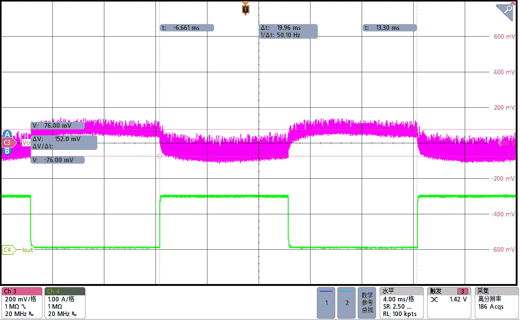
PMP41015 Output Voltage VOUT and Output
                        Current IOUT Waveform at Load Transient, 230VACFigure 3-14 Output Voltage VOUT and Output Current IOUT Waveform at Load Transient, 230VAC