TIDT376 December 2023
2.3 Thermal Data
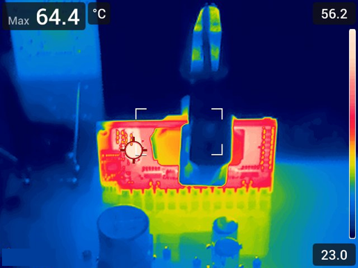
Figure 3-9 shows the thermal image. The heat sink has been removed and the applied load is 500 W.
 Figure 2-2 Thermal Image
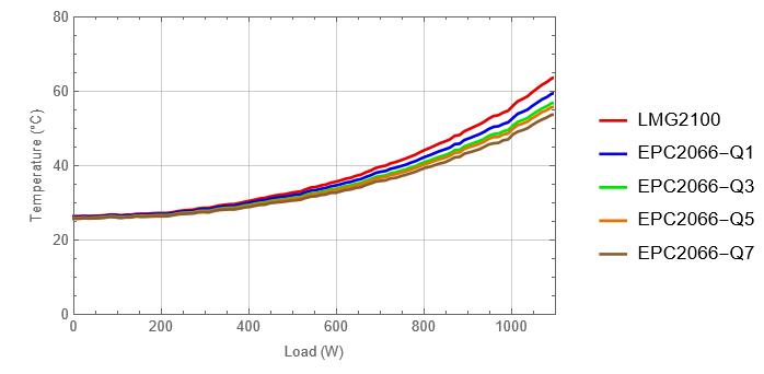
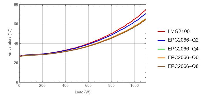
FET temperatures were also measured with thermocouples. The heat sink and the thermal interface material (TIM) were applied for these measurements. The TIM used is LiPOLY T-work9000 with 1-mm thickness.
 Figure 2-3 Thermocouple Data - Top
Side Components
 Figure 2-4 Thermocouple Data - Bottom
Side Components