TIDT382
February 2024
1
Description
Features
Applications
1
Test Prerequisites
1.1
Voltage and Current Requirements
1.2
Considerations
1.3
Dimensions
2
Testing and Results
2.1
Efficiency Graphs
2.1.1
LM25180-Q1 Efficiency Graph
2.1.2
SN6507-Q1 Efficiency Graph
2.1.3
UCC14130-Q1 Efficiency Graph
2.1.4
UCC25800-Q1 Efficiency Graph
2.1.5
Efficiency Comparison
2.2
Efficiency Data
2.2.1
LM25180-Q1 Efficiency Data
2.2.2
SN6507-Q1 Efficiency Data
2.2.3
UCC14130-Q1 Efficiency Data
2.2.4
UCC25800-Q1 Efficiency Data
2.3
Load Regulation
2.3.1
LM25180-Q1 Load Regulation
2.3.2
SN6507-Q1 Load Regulation
2.3.3
UCC14130-Q1 Load Regulation
2.3.4
UCC25800-Q1 Load Regulation
2.3.5
Load Regulation Comparison
2.4
Thermal Images
2.4.1
LM25180-Q1 Thermal Image
2.4.2
SN6507-Q1 Thermal Image
2.4.3
UCC14130-Q1 Thermal Image
2.4.4
UCC25800-Q1 Thermal Image
2.5
Common-Mode Current (CMI)
2.5.1
LM25180-Q1 CMI
2.5.2
SN6507-Q1 CMI
2.5.3
UCC14130-Q1 CMI
2.5.4
UCC25800-Q1 CMI
2.5.5
Common-Mode Current Comparison
3
Waveforms
3.1
Switching
3.1.1
LM25180-Q1 Switching
3.1.2
SN6507-Q1 Switching
3.1.3
UCC25800-Q1 Switching
3.2
Output Voltage Ripple
3.2.1
LM25180-Q1 Output Voltage Ripple
3.2.2
SN6507-Q1 Output Voltage Ripple
3.2.3
UCC14130-Q1 Output Voltage Ripple
3.2.4
UCC25800-Q1 Output Voltage Ripple
3.2.5
Output Voltage Ripple Comparison
3.3
Input Voltage Ripple
3.3.1
LM25180-Q1 Input Voltage Ripple
3.3.2
SN6507-Q1 Input Voltage Ripple
3.3.3
UCC14130-Q1 Input Voltage Ripple
3.3.4
UCC25800-Q1 Input Voltage Ripple
3.3.5
Input Voltage Ripple Comparison
3.4
Load Transients
3.4.1
LM25180-Q1 Load Transients
3.4.2
SN6507-Q1 Load Transients
3.4.3
UCC14130-Q1 Load Transients
3.4.4
UCC25800-Q1 Load Transients
3.5
Start-Up Sequence
3.5.1
LM25180-Q1 Start-Up Sequence
3.5.2
SN6507 Q1 Start Up Sequence
3.5.3
UCC14130-Q1 Start-Up Sequence
3.5.4
UCC25800-Q1 Start-Up Sequence
3.6
Shutdown Sequence
3.6.1
LM25180-Q1 Shutdown Sequence
3.6.2
SN6507-Q1 Shutdown Sequence
3.6.3
UCC14130-Q1 Shutdown Sequence
3.6.4
UCC25800-Q1 Shutdown Sequence
3.7
Undervoltage Protection
3.7.1
LM25180-Q1 Undervoltage Protection
3.7.2
SN6507-Q1 Undervoltage Protection
3.7.3
UCC14130-Q1 Undervoltage Protection
3.7.4
UCC25800-Q1 Undervoltage Protection
4
Summary
5
References
2.5.2
SN6507-Q1 CMI
The SN6507-Q1 CMI waveforms are illustrated in the following images.
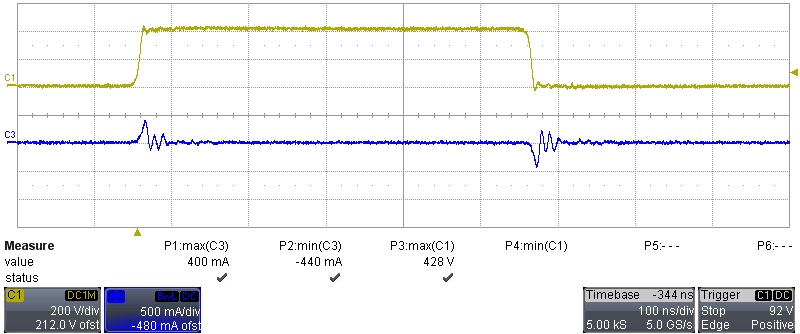
Channel 1: HV switch node, [scale: 200V/div, 100ns/div]
Channel 3: CMI current, [scale: 500mA/div, 100ns/div]
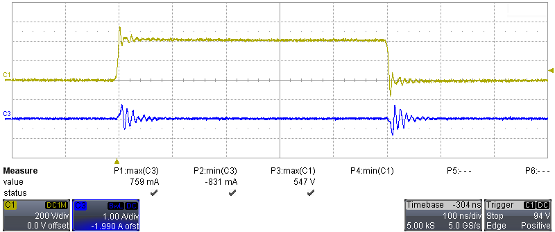
Figure 2-18
Common-Mode Current at 40V/ns Slew Rate
Channel 1: HV switch node, [scale: 200V/div, 100ns/div]
Channel 3: CMI current, [scale: 1A/div, 100ns/div]
Figure 2-19
Common-Mode Current at 100V/ns Slew Rate