TIDT384 February 2024
2.3 Dimensions
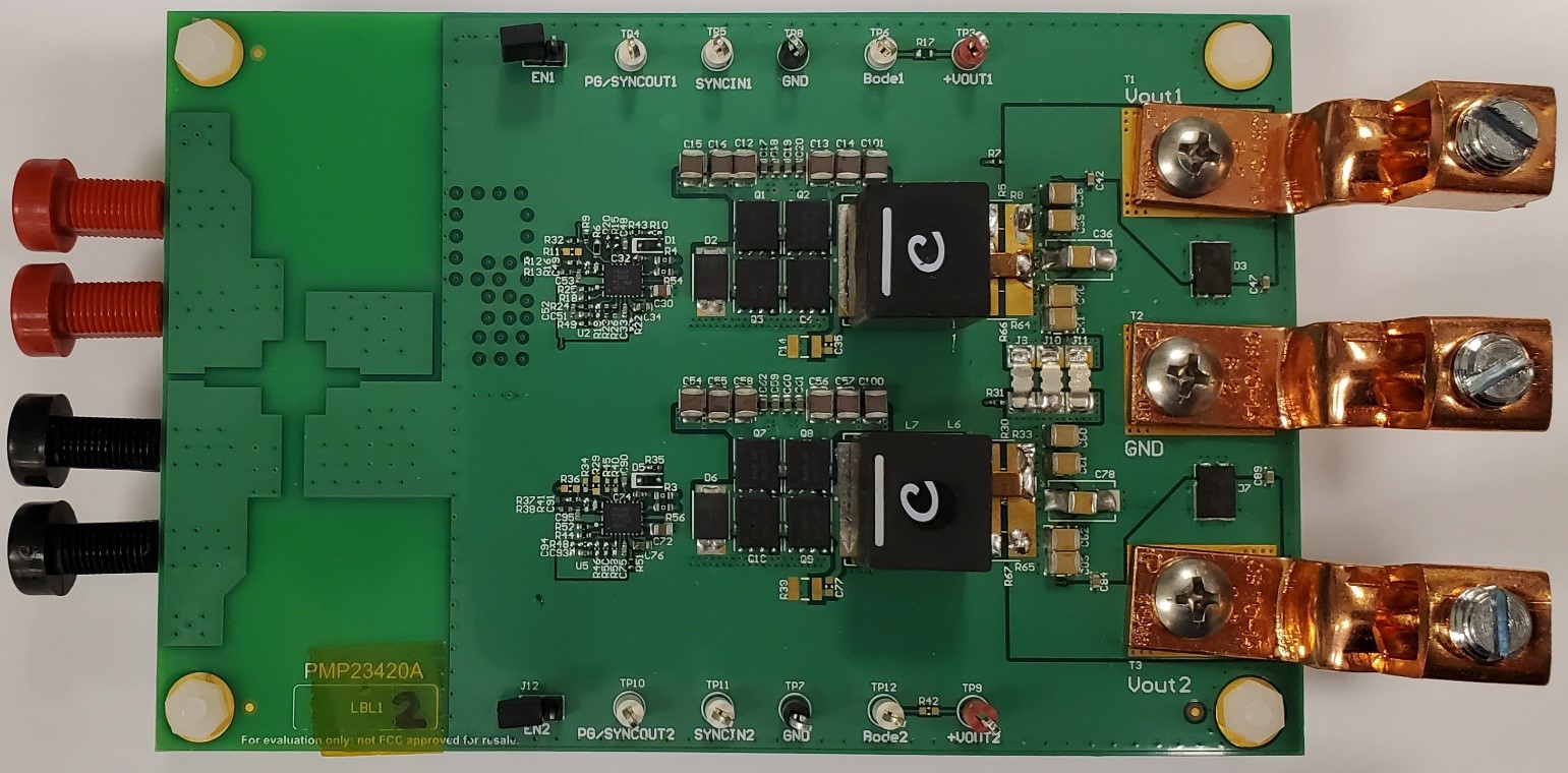
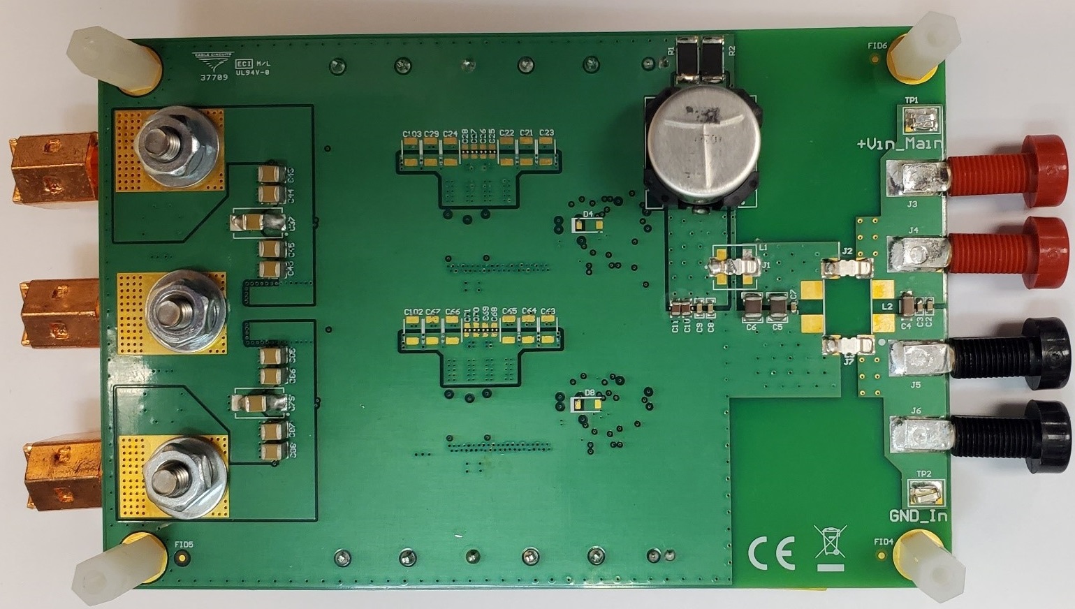
Figure 2-14 and Figure 2-15 present the top and bottom photos of the PMP23420 board, respectively. The board dimensions are 5.2in × 3.4in (132.08mm × 86.36mm). Remember that this is an evaluation board and has plenty of unutilized space, for ease of testing. The final design size can be significantly reduced to approximately 55mm × 53mm (or smaller), when omitting the low-side Schottky diodes, which are not absolutely necessary, and pushing the controller circuitry closer to the FETs.

Figure 2-14 Top of PMP23420 Board

Figure 2-15 Bottom of PMP23420 Board